
Chapter 1
Aircraft Engines
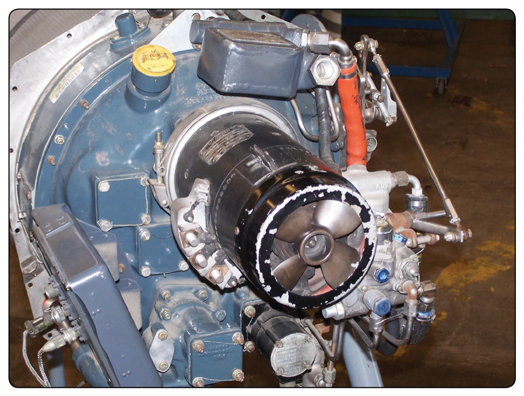
compressors are limited to two stages due to efficiency concerns. The two main functional elements are the impeller and the diffuser. Although the diffuser is a separate unit and is placed inside and bolted to the manifold, the entire assembly (diffuser and manifold) is often referred to as the diffuser. For clarification during compressor familiarization, the units are treated individually. The impeller is usually made from forged aluminum alloy, heat treated, machined, and smoothed for minimum flow restriction and turbulence.
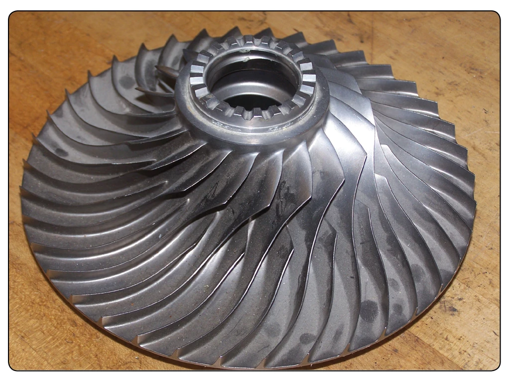
In most types, the impeller is fabricated from a single forging. This type impeller is shown in Figure 1-46. The impeller, whose function is to pick up and accelerate the air outwardly to the diffuser, may be either of two types—single entry or double entry. The principal differences between the two types of impellers are size and ducting arrangement. The double-entry type has a smaller diameter but is usually operated at a higher rotational speed to assure sufficient airflow. The single-entry impeller, shown in Figure 1-47, permits convenient ducting directly to the impeller eye (inducer vanes) as opposed to the more complicated ducting necessary to reach the rear side of the double-entry type. Although slightly more efficient in receiving air, the singleentry impeller must be large in diameter to deliver the same quantity of air as the double-entry type. This, of course, increases the overall diameter of the engine.
Included in the ducting for double-entry compressor engines is the plenum chamber. This chamber is necessary for a double-entry compressor because the air must enter the engine at almost right angles to the engine axis. Therefore, in order to give a positive flow, the air must surround the engine compressor at a positive pressure before entering the compressor. Included in some installations as necessary parts of the plenum chamber are the auxiliary air-intake doors (blow-in doors). These blow-in doors admit air to the engine compartment during ground operation, when air requirements for the engine are in excess of the airflow through the inlet ducts. The doors are held closed by spring action when the engine is not operating. During operation, however, the doors open automatically whenever engine compartment pressure drops below atmospheric pressure. During takeoff and flight, ram air pressure in the engine compartment aids the springs in holding the doors closed.
The diffuser is an annular chamber provided with a number of vanes forming a series of divergent passages into the manifold. The diffuser vanes direct the flow of air from the impeller to the manifold at an angle designed to retain the maximum amount of energy imparted by the impeller. They also deliver the air to the manifold at a velocity and pressure satisfactory for use in the combustion chambers. Refer to Figure 1-46A and note the arrow indicating the path of airflow through the diffuser, then through the manifold.
The compressor manifold shown in Figure 1-46A diverts the flow of air from the diffuser, which is an integral part of the manifold, into the combustion chambers. The manifold has one outlet port for each chamber so that the air is evenly divided. A compressor outlet elbow is bolted to each of the outlet ports. These air outlets are constructed in the form of ducts and are known by a variety of names, such as air outlet ducts, outlet elbows, or combustion chamber inlet ducts. Regardless of the terminology used, these outlet ducts perform a very important part of the diffusion process; that is, they change the radial direction of the airflow to an axial direction, in which the diffusion process is completed after the turn. To help the elbows perform this function in an efficient manner, turning vanes (cascade vanes) are sometimes fitted inside the elbows. These vanes reduce air pressure losses by
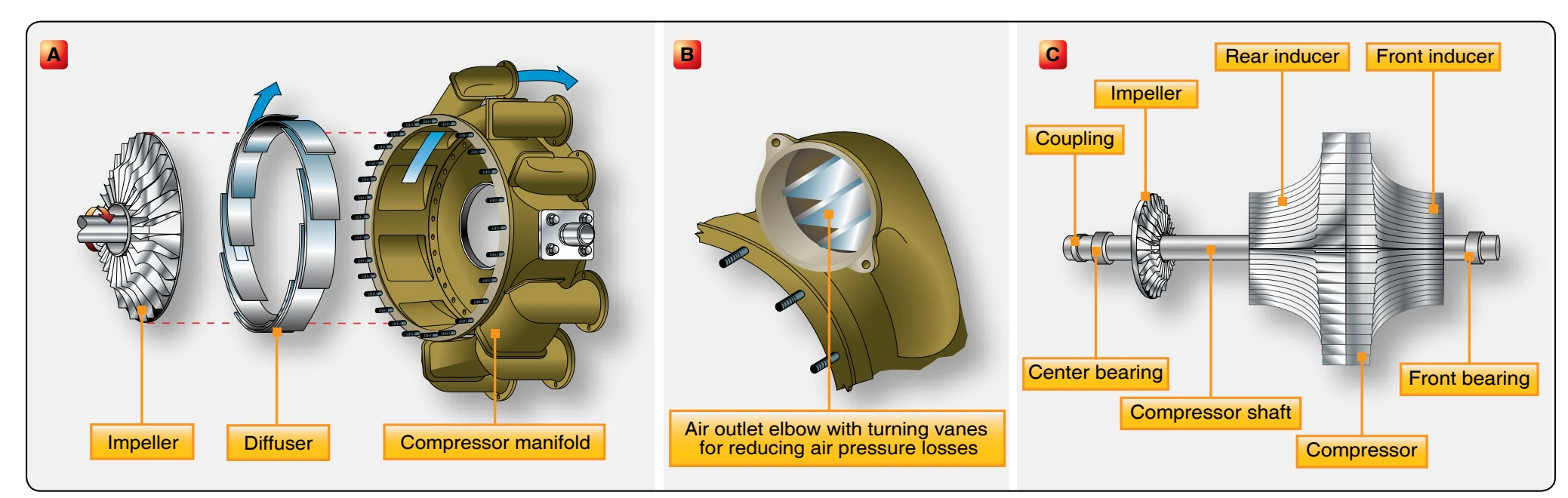
presenting a smooth, turning surface. [Figure 1-46B]
Axial-Flow Compressor
The axial flow compressor is a combination of an engine compressor and high-pressure turbine that drives it using a connecting drive shaft. In a single-spool engine, the highpressure turbine drives the entire compressor. In a dual-spool engine, the compressor and high-pressure turbine are both split into two segments. Each compressor segment is driven by its corresponding turbine using two separate drive shafts, with one inside the other. The first stage turbine drives the N2 compressor.
The axial-flow compressor has two main elements: a rotor and a stator. The rotor has blades fixed on a spindle. These blades impel air rearward in the same manner as a propeller because of their angle and airfoil contour. The rotor, turning at high speed, takes in air at the compressor inlet and impels it through a series of stages. From inlet to exit, the air flows along an axial path and is compressed at a ratio of approximately 1.25:1 per stage. The action of the rotor increases the compression of the air at each stage and accelerates it rearward through several stages. With this increased velocity, energy is transferred from the compressor to the air in the form of velocity energy. The stator blades act as diffusers at each stage, partially converting high velocity to pressure. Each consecutive pair of rotor and stator blades constitutes a pressure stage. The number of rows of blades (stages) is determined by the amount of air and total pressure rise required. Compressor pressure ratio increases with the number of compression stages. Most engines utilize up to 16 stages and more.
The stator has rows of vanes, which are in turn attached inside an enclosing case. The stator vanes, which are stationary, project radially toward the rotor axis and fit closely on either side of each stage of the rotor blades. In some cases, the compressor case, into which the stator vanes are fitted, is horizontally divided into halves. Either the upper or lower half may be removed for inspection or maintenance of rotor and stator blades.
The function of the stator vanes is to receive air from the air inlet duct or from each preceding stage and increase the pressure of the air and deliver it to the next stage at the correct velocity and pressure. They also control the direction of air to each rotor stage to obtain the maximum possible compressor blade efficiency. Shown in Figure 1-48 are the rotor and stator elements of a typical axial-flow compressor. The first stage rotor blades can be preceded by an inlet guide vane assembly that can be fixed or variable.
The guide vanes direct the airflow into the first stage rotor blades at the proper angle and impart a swirling motion to the air entering the compressor. This preswirl, in the direction of engine rotation, improves the aerodynamic characteristics of the compressor by reducing drag on the first stage rotor blades. The inlet guide vanes are curved steel vanes usually welded to steel inner and outer shrouds.
At the discharge end of the compressor, the stator vanes are constructed to straighten the airflow to eliminate turbulence. These vanes are called straightening vanes or the outlet vane assembly. The casings of axial-flow compressors not only support the stator vanes and provide the outer wall of the axial path the air follows, but they also provide the means for extracting compressor air for various purposes. The stator vanes are usually made of steel with corrosion- and erosionresistant qualities. Quite frequently, they are shrouded (enclosed) by a band of suitable material to simplify the fastening problem. The vanes are welded into the shrouds, and the outer shroud is secured to the compressor housing inner wall by radial retaining screws.
The rotor blades are usually made of stainless steel with the latter stages being made of titanium. The design of blade attachment to the rotor disc rims varies, but they are commonly fitted into discs by either bulb-type or fir-tree methods. [Figure 1-49] The blades are then locked into place by differing methods. Compressor blade tips are reduced
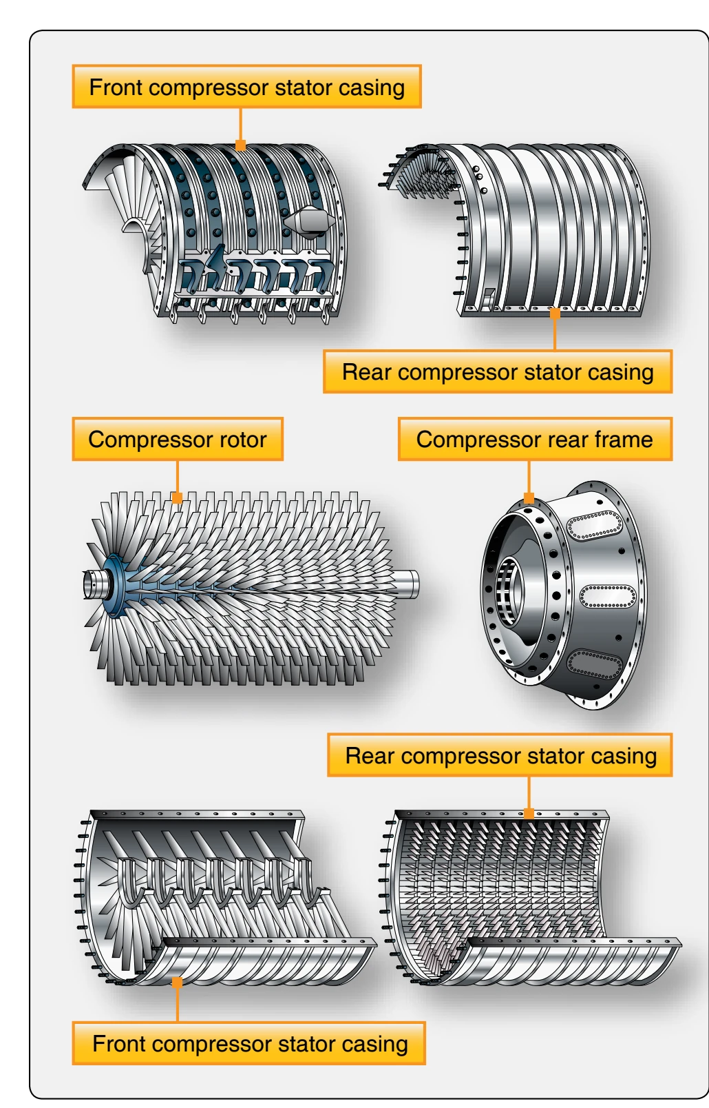
in thickness by cutouts, referred to as blade profiles. These profiles prevent serious damage to the blade or housing should the blades contact the compressor housing. This condition can occur if rotor blades become excessively loose or if rotor support is reduced by a malfunctioning bearing. Even though blade profiles greatly reduce such possibilities, occasionally a blade may break under stress of rubbing and cause considerable damage to compressor blades and stator vane assemblies. The blades vary in length from entry to discharge because the annular working space (drum to casing) is reduced progressively toward the rear by the decrease in the casing diameter. [Figure 1-50] This feature provides for a fairly constant velocity through the compressor, which helps to keep the flow of air constant.
The rotor features either drum-type or disc-type construction. The drum-type rotor consists of rings that are flanged to fit one against the other, wherein the entire assembly can then be held together by through bolts. This type of construction is satisfactory for low-speed compressors where centrifugal stresses are low. The disc-type rotor consists of a series of discs machined from aluminum forgings, shrunk over a steel shaft, with rotor blades dovetailed into the disc rims. Another method of rotor construction is to machine the discs and shaft from a single aluminum forging, and then to bolt steel stub shafts on the front and rear of the assembly to provide bearing support surfaces and splines for joining the turbine shaft. The drum-type and disc-type rotors are illustrated in Figures 1-50 and 1-51, respectively.