
Chapter 1
Aircraft Engines
The combination of the compressor stages and turbine stages on a common shaft is an engine referred to as an engine spool. The common shaft is provided by joining the turbine and compressor shafts by a suitable method. The engine’s spool is supported by bearings, which are seated in suitable bearing housings.
As mentioned earlier, there are two configurations of the axial compressor currently in use: the single rotor/spool and the dual rotor/spool, sometimes referred to as solid spool and split spool (two spool, dual spool).
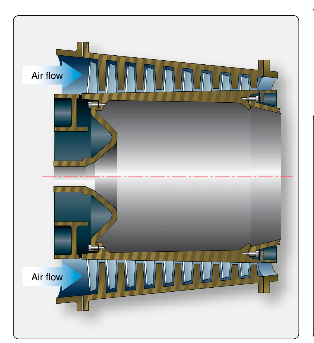
One version of the solid-spool (one spool) compressor uses variable inlet guide vanes. Also, the first few rows of stator vanes are variable. The main difference between variable inlet guide vane (VIGV) and a variable stator vane (VSV) is their position with regard to the rotor blades. VIGV are in front of the rotor blades, and VSV are behind the rotor blades. The angles of the inlet guide vanes and the first several stages of the stator vanes are can be variable. During operation, air enters the front of the engine and is directed into the compressor at the proper angle by the variable inlet guide and directed by the VSV. The air is compressed and forced into the combustion
section. A fuel nozzle that extends into each combustion liner atomizes the fuel for combustion. These variables are controlled in direct relation to the amount of power the engine is required to produce by the power lever position.
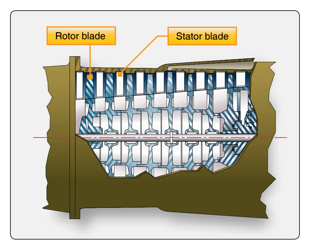
Most turbofan engines are of the split-spool compressor type. Most large turbofan engines use a large fan with a few stages of compression called the low-pressure spool. These turbofans incorporate two compressors with their respective turbines and interconnecting shafts, which form two physically independent
rotor systems. Many dual rotor systems have rotors turning in opposite directions and with no mechanical connection to each other. The second spool, referred to as the high-pressure spool and is the compressor for the gas generator and core of the engine, supplies air to the combustion section of the engine.
The advantages and disadvantages of both types of compressors are included in the following list. Even though each type has advantages and disadvantages, each has its use by type and size of engine.
The centrifugal-flow compressor’s advantages are:
- High pressure rise per stage,
- Efficiency over wide rotational speed range,
- Simplicity of manufacture and low cost,
- Low weight, and
- Low starting power requirements.
The centrifugal-flow compressor’s disadvantages are:
- Its large frontal area for a given airflow and
- Losses in turns between stages.
The axial-flow compressor’s advantages are:
- High peak efficiencies;
- Small frontal area for given airflow;
- Straight-through flow, allowing high ram efficiency; and
- Increased pressure rise by increasing number of stages, with negligible losses.
The axial-flow compressor’s disadvantages are:
- Good efficiencies over only narrow rotational speed range,
- Difficulty of manufacture and high cost,
- Relatively high weight, and
- High starting power requirements (partially overcome by split compressors).