
Chapter 1
Aircraft Engines
The diffuser is the divergent section of the engine after the compressor and before the combustion section. It has the all-important function of reducing high-velocity compressor discharge air to increased pressure at a slower velocity. This prepares the air for entry into the flame burning area of the combustion section at a lower velocity so that the flame of combustion can burn continuously. If the air passed through the flame area at a high velocity, it could extinguish the flame.
Combustion Section
The combustion section houses the combustion process, which raises the temperature of the air passing through the engine. This process releases energy contained in the airfuel mixture. The major part of this energy is required at the turbine or turbine stages to drive the compressor. About ²⁄ of ³ the energy is used to drive the gas generator compressor. The remaining energy passes through the remaining turbine stages that absorb more of the energy to drive the fan, output shaft, or propeller. Only the pure turbojet allows the air to create all the thrust or propulsion by exiting the rear of the engine in the form of a high-velocity jet. These other engine types have some jet velocity out the rear of the engine but most of the thrust or power is generated by the additional turbine stages driving a large fan, propeller, or helicopter rotor blades.
The primary function of the combustion section is, of course, to burn the air-fuel mixture, thereby adding heat energy to the air. To do this efficiently, the combustion chamber must:
- Provide the means for proper mixing of the fuel and air to assure good combustion,
- Burn this mixture efficiently,
- Cool the hot combustion products to a temperature that the turbine inlet guide vanes/blades can withstand under operating conditions, and
- Deliver the hot gases to the turbine section.
The location of the combustion section is directly between the compressor and the turbine sections. The combustion chambers are always arranged coaxially with the compressor and turbine regardless of type, since the chambers must be in a through-flow position to function efficiently. All combustion chambers contain the same basic elements:
- Casing.
- Perforated inner liner.
- Fuel injection system.
- Some means for initial ignition.
- Fuel drainage system to drain off unburned fuel after engine shutdown.
There are currently four basic types of combustion chambers, variations within type being in detail only. These types are:
- Can-type.
- Can-annular type.
- Annular type.
- Reverse-flow type.
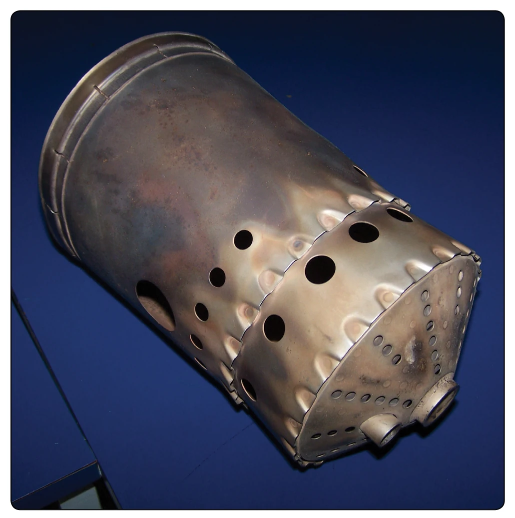
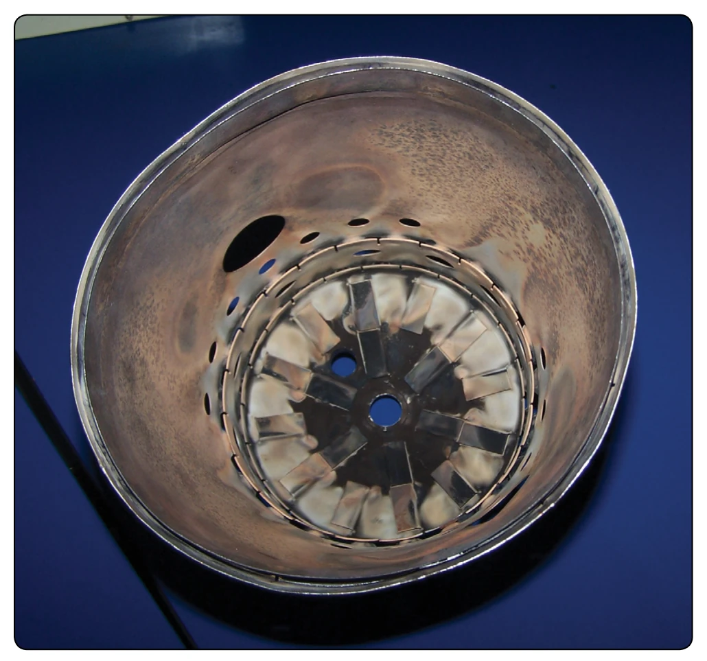
The can-type combustion chamber is typical of the type used on turboshaft and APUs. [Figure 1-52] Each of the can-type combustion chambers consists of an outer case or housing, within which there is a perforated stainless steel (highly heat resistant) combustion chamber liner or inner liner. [Figure 1-53] The outer case is removed to facilitate liner replacement.
Older engines with several combustion cans had each can with interconnector (flame propagation) tube, which was a necessary part of the can-type combustion chambers. Since each can is a separate burner operating independently of the other cans, there must be some way to spread combustion during the initial starting operation. This is accomplished by interconnecting all the chambers. As the flame is started by the spark igniter plugs in two of the lower chambers, it passes through the tubes and ignites the combustible mixture in the adjacent chamber and continues until all the chambers
are burning.
The flame tubes vary in construction details from one engine to another, although the basic components are almost identical. [Figure 1-54] The spark igniters previously mentioned are normally two in number and are located in two of the can-type combustion chambers.
Another very important requirement in the construction of combustion chambers is providing the means for draining unburned fuel. This drainage prevents gum deposits in the fuel manifold, nozzles, and combustion chambers. These deposits are caused by the residue left when the fuel evaporates. Probably most important is the danger of afterfire if the fuel is allowed to accumulate after shutdown. If the fuel is not drained, a great possibility exists that, at the next starting attempt, the excess fuel in the combustion chamber will ignite and exhaust gas temperature will exceed safe operating limits.
The liners of the can-type combustors have perforations of various sizes and shapes, each hole having a specific purpose and effect on flame propagation within the liner. [Figure 1-52] The air entering the combustion chamber is divided by the proper holes, louvers, and slots into two main streams—primary and secondary air. The primary or combustion air is directed inside the liner at the front end, where it mixes with the fuel and is burned. Secondary or cooling air passes between the outer casing and the liner and joins the combustion gases through larger holes toward the rear of the liner, cooling the combustion gases from about 3,500 °F to near 1,500 °F. To aid in atomization of the fuel, holes are provided around the fuel nozzle in the dome or inlet end of the can-type combustor liner. Louvers are also provided along the axial length of the liners to direct a cooling layer of air along the inside wall of the liner. This layer of air also tends to control the flame pattern by keeping it centered in the liner, thereby preventing burning of the liner walls. Figure 1-55 illustrates the annular combustion chamber liner.
Some provision is always made in the combustion chamber case for installation of a fuel nozzle. The fuel nozzle delivers the fuel into the liner in a finely atomized spray. The more the spray is atomized, the more rapid and efficient the burning process is.
Two types of fuel nozzle currently being used in the various types of combustion chambers are the simplex nozzle and the duplex nozzle. The construction features of these nozzles are covered in greater detail in Chapter 2, Engine Fuel & Fuel Metering Systems.
The spark igniter plugs of the annular combustion chamber are the same basic type used in the can-type combustion chambers, although construction details may vary. There are usually two igniters mounted on the boss provided on each of the chamber housings. The igniters must be long enough to protrude from the housing into the combustion chamber.