
Chapter 1
Aircraft Engines
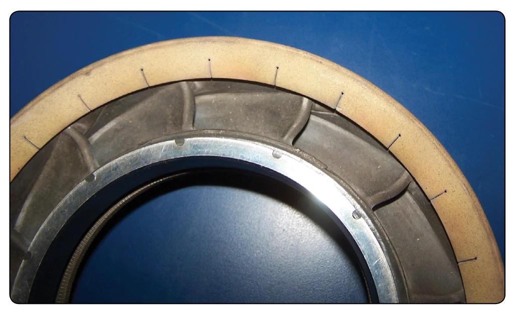
The turbine inlet nozzle vanes are located directly aft of the combustion chambers and immediately forward of the turbine wheel. This is the highest or hottest temperature that comes in contact with metal components in the engine. The turbine inlet temperature must be controlled, or damage will occur to the turbine inlet vanes.
After the combustion chamber has introduced the heat energy into the mass airflow and delivered it evenly to the turbine
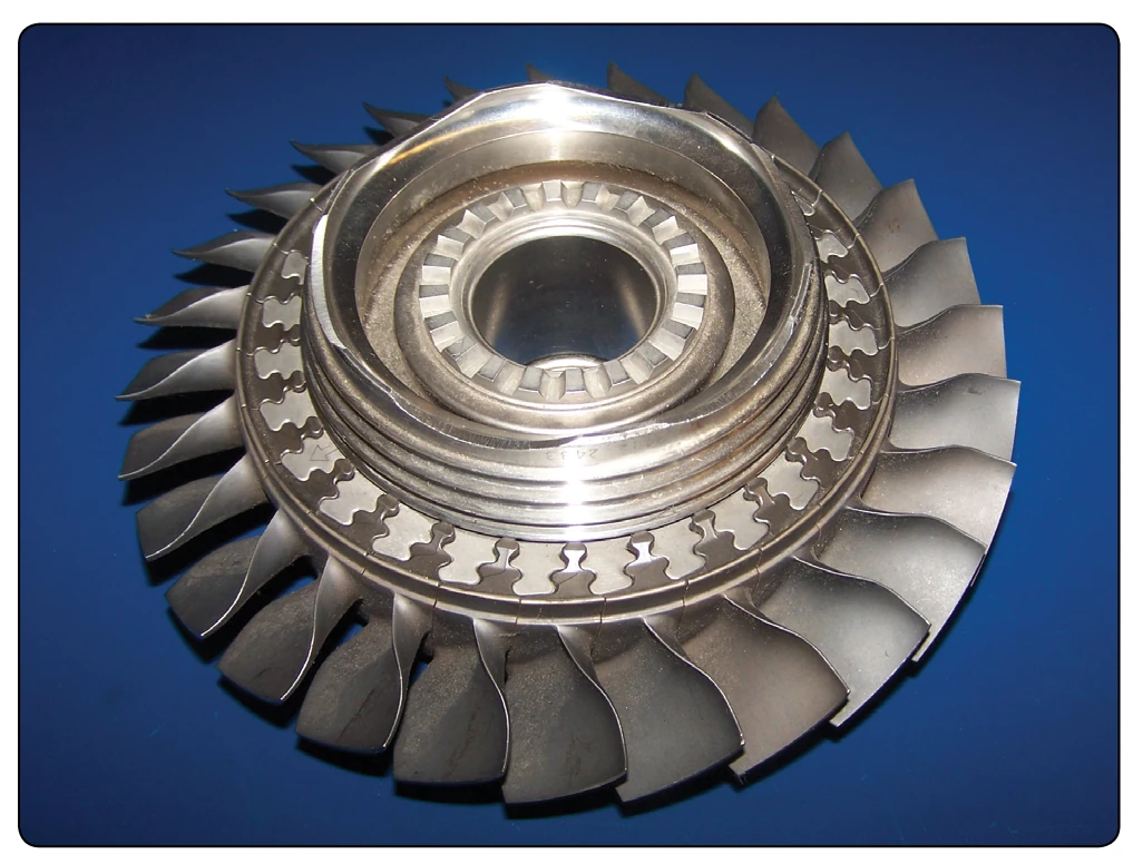
inlet nozzles, the nozzles must prepare the mass air flow to drive the turbine rotor. The stationary vanes of the turbine inlet nozzles are contoured and set at such an angle that they form a number of small nozzles discharging gas at extremely high speed; thus, the nozzle converts a varying portion of the heat and pressure energy to velocity energy that can then be converted to mechanical energy through the turbine blades.
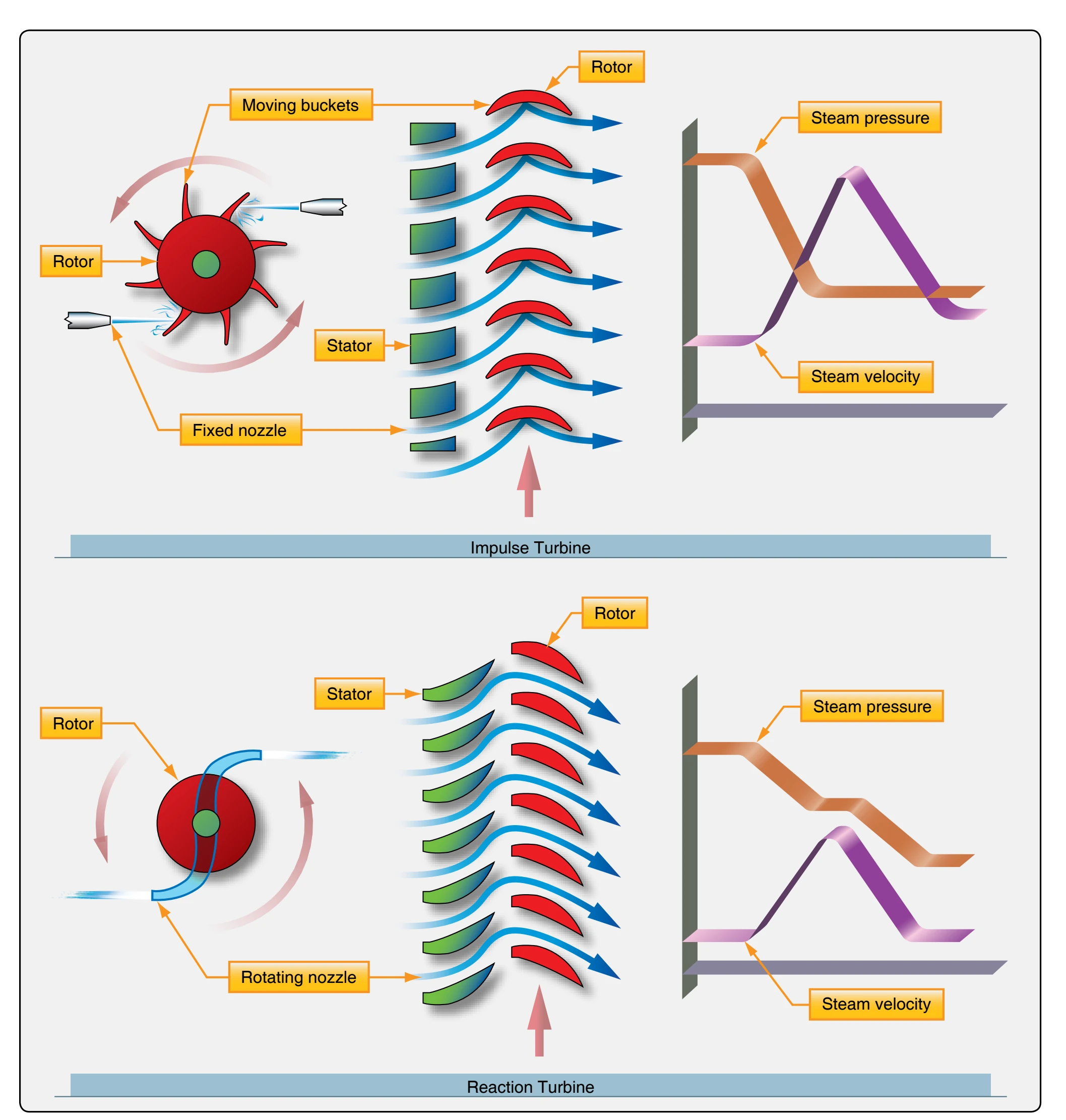
There are three types of turbine blades: the impulse turbine blade, reaction turbine blade, and the reaction-impulse turbine blade. The impulse turbine blade is also referred to as a bucket. This is because as the stream of air strikes the center of the blade it changes the direction of the energy as it causes the blades to rotate the disc and rotor shaft. The turbine nozzle guide vanes can usually be adjusted during engine overhaul and assembly in order to increase the efficiency of the air stream striking the blades or buckets of the turbine. [Figure 1-62]
Reaction turbine blades cause the disc to rotate by the aerodynamic action of the airstream directed to flow past the blade at a particular angle in order to develop the most efficient power from the turbine engine. [Figure 1-62]
The reaction-impulse turbine blade combines the action of both the impulse and reaction blades designs. The blade has more of the bucket shape of the impulse blade at the blade root and it also has more of an airfoil shape of the reaction blade on the second half of the blade toward the outer end of the blade.
The second purpose of the turbine inlet nozzle is to deflect the gases to a specific angle in the direction of turbine wheel rotation. Since the gas flow from the nozzle must enter the turbine blade passageway while it is still rotating, it is essential to aim the gas in the general direction of turbine rotation.
The turbine inlet nozzle assembly consists of an inner shroud and an outer shroud between which the nozzle vanes are fixed. The number and size of inlet vanes employed vary with different types and sizes of engines. Figure 1-63 illustrates typical turbine inlet nozzles featuring loose and welded vanes. The vanes of the turbine inlet nozzle may be assembled between the outer and inner shrouds or rings in a variety of ways. Although the actual elements may vary slightly in configuration and construction features, there is one characteristic peculiar to all turbine inlet nozzles: the nozzle vanes must be constructed to allow thermal expansion. Otherwise, there would be severe distortion or warping of the metal components because of rapid temperature changes.
The thermal expansion of turbine nozzles is accomplished by one of several methods. One method necessitates loose assembly of the supporting inner and outer vane shrouds. [Figure 1-63A]
Each vane fits into a contoured slot in the shrouds, which conforms to the airfoil shape of the vane. These slots are slightly larger than the vanes to give a loose fit. For further support, the inner and outer shrouds are encased by inner and outer support rings, which provide increased strength and rigidity. These support rings also facilitate removal of the nozzle vanes as a unit. Without the rings, the vanes could fall out as the shrouds were removed.
Another method of thermal expansion construction is to fit the vanes into inner and outer shrouds; however, in this method the vanes are welded or riveted into position. [Figure 1-63B] Some means must be provided to allow thermal expansion; therefore, either the inner or the outer shroud ring is cut into segments. The saw cuts separating the segments allow sufficient expansion to prevent stress and warping of the vanes.
The rotor element of the turbine section consists essentially of a shaft and a wheel. [Figure 1-64] The turbine wheel is a dynamically balanced unit consisting of blades attached to a rotating disc. The disc, in turn, is attached to the main power-transmitting shaft of the engine. The exhaust gases leaving the turbine inlet nozzle vanes act on the blades of the turbine wheel, causing the assembly to rotate at a very high rate of speed. The high rotational speed imposes severe centrifugal loads on the turbine wheel, and at the same time the elevated temperatures result in a lowering of the strength of the material. Consequently, the engine speed and temperature must be controlled to keep turbine operation within safe limits.
The turbine disc is referred to as such without blades. When the turbine blades are installed, the disc then becomes the turbine wheel. The disc acts as an anchoring component for the turbine blades. Since the disc is bolted or welded to the
shaft, the blades can transmit to the rotor shaft the energy they extract from the exhaust gases.
The disc rim is exposed to the hot gases passing through the blades and absorbs considerable heat from these gases. In addition, the rim also absorbs heat from the turbine blades by conduction. Hence, disc rim temperatures are normally high and well above the temperatures of the more remote inner portion of the disc. As a result of these temperature gradients, thermal stresses are added to the rotational stresses.
Additionally, turbine blades are generally more susceptible to operating damage than compressor blades due to the exposure of high temperatures. There are various methods to relieve, at least partially, the aforementioned stresses. One such method is to bleed cooling air back onto the face of the disc.
Another method of relieving the thermal stresses of the disc is incidental to blade installation. A series of grooves or notches, conforming to the blade root design, are broached in the rim of the disc. These grooves allow attachment of the