
Chapter 1
Aircraft Engines
turbine blades to the disc; at the same time, space is provided by the notches for thermal expansion of the disc. Sufficient clearance exists between the blade root and the notch to permit movement of the turbine blade when the disc is cold. During engine operation, expansion of the disc decreases the clearance. This causes the blade root to fit tightly in the disc rim.
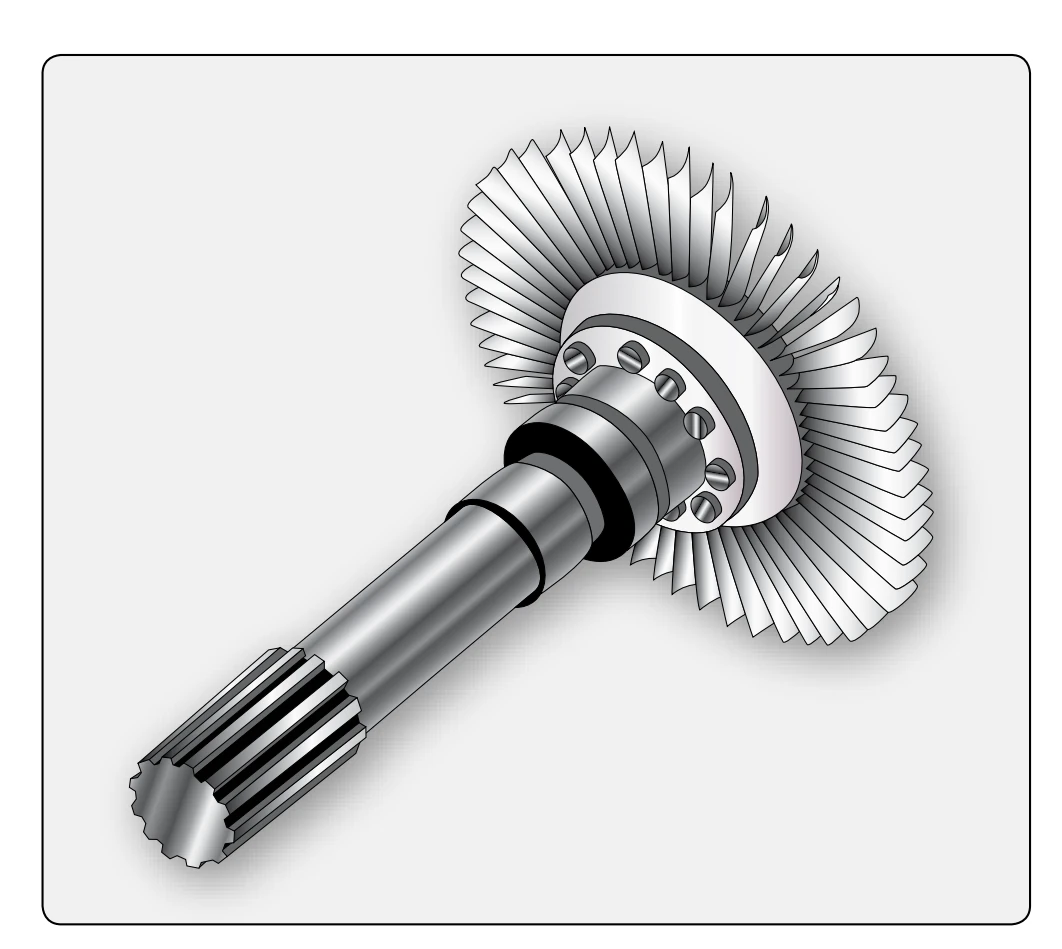
The turbine shaft is usually fabricated from alloy steel. [Figure 1-64] It must be capable of absorbing the high torque loads that are exerted on it.
The methods of connecting the shaft to the turbine disc vary. In one method, the shaft is welded to the disc, which has a butt or protrusion provided for the joint. Another method is by bolting. This method requires that the shaft have a hub that fits a machined surface on the disc face. Then, the bolts are inserted through holes in the shaft hub and anchored in tapped holes in the disc. Of the two connection methods, bolting is more common.
The turbine shaft must have some means for attachment to the compressor rotor hub. This is usually accomplished by a spline cut on the forward end of the shaft. The spline fits into a coupling device between the compressor and turbine shafts. If a coupling is not used, the splined end of the turbine shaft may fit into a splined recess in the compressor rotor hub. This splined coupling arrangement is used almost exclusively with centrifugal compressor engines, while axial compressor engines may use either of these described methods.
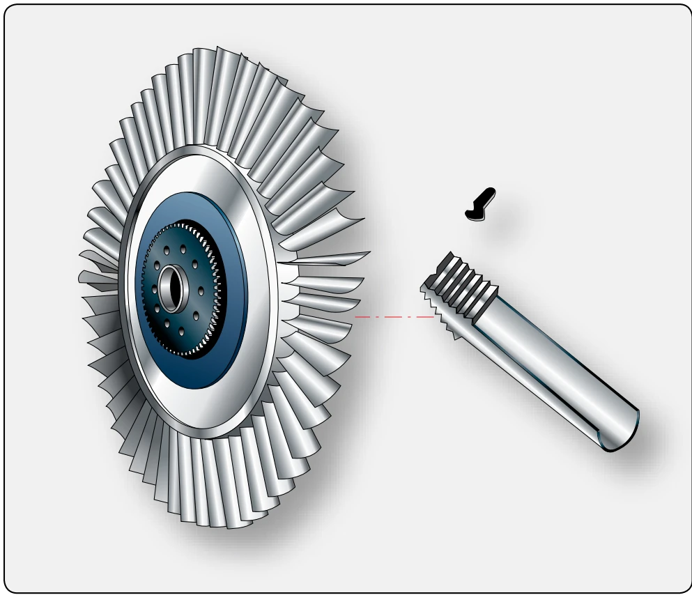
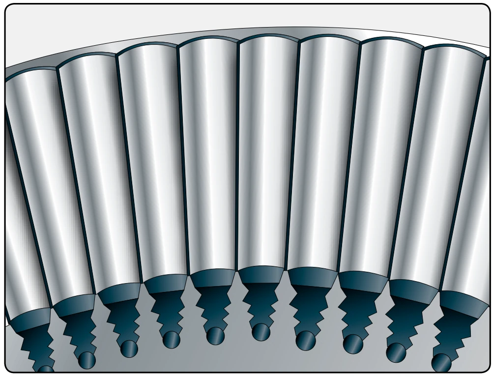
There are various ways of attaching turbine blades, some similar to compressor blade attachment. The most satisfactory method utilizes the fir-tree design. [Figure 1-65]
The blades are retained in their respective grooves by a variety of methods, the more common of which are peening, welding, lock tabs, and riveting. Figure 1-66 shows a typical turbine wheel using rivets for blade retention.
The peening method of blade retention is used frequently in various ways. One of the most common applications of peening requires a small notch to be ground in the edge of the blade fir-tree root prior to the blade installation. After the blade is inserted into the disc, the notch is filled by the disc metal, which is “flowed” into it by a small punch-mark made in the disc adjacent to the notch. The tool used for this job is similar to a center punch.
Another method of blade retention is to construct the root of the blade so that it contains all the elements necessary for its retention. This method uses the blade root as a stop made on one end of the root so that the blade can be inserted and removed in one direction only, while on the opposite end is a tang. This tang is bent to secure the blade in the disc.
Turbine blades may be either forged or cast, depending on the composition of the alloys. Most blades are precision cast and finish ground to the desired shape. Many turbine blades are cast as a single crystal, which gives the blades better strength and heat properties. Heat barrier coating, such as ceramic coating, and air flow cooling help keep the turbine blades and inlet nozzles cooler. This allows the exhaust temperature to be raised, increasing the efficiency of the engine. Figure 1-67
shows a turbine blade with air holes for cooling purposes.
Most turbines are open at the outer perimeter of the blades; however, a second type called the shrouded turbine is sometimes used. The shrouded turbine blades, in effect, form a band around the outer perimeter of the turbine wheel. This improves efficiency and vibration characteristics and permits lighter stage weights. On the other hand, it limits turbine speed and requires more blades. [Figure 1-68]
In turbine rotor construction, it occasionally becomes necessary to utilize turbines of more than one stage. A single turbine wheel often cannot absorb enough power from the exhaust gases to drive the components dependent on the turbine for rotative power; thus, it is necessary to add additional turbine stages.
A turbine stage consists of a row of stationary vanes or nozzles, followed by a row of rotating blades. In some models of turboprop engine, as many as five turbine stages have been utilized successfully. It should be remembered that, regardless of the number of wheels necessary for driving engine components, there is always a turbine nozzle preceding each wheel.
As was brought out in the preceding discussion of turbine stages, the occasional use of more than one turbine wheel is warranted in cases of heavy rotational loads. It should also be pointed out that the same loads that necessitate multistage turbines often make it advantageous to incorporate multiple compressor rotors.
In the single-stage rotor turbine, the power is developed by one turbine rotor, and all engine-driven parts are driven by
this single wheel. [Figure 1-69] This arrangement is used on engines where the need for low weight and compactness predominates. This is the simplest version of the pure turbojet engine.