Chapter 1
Aircraft Engines
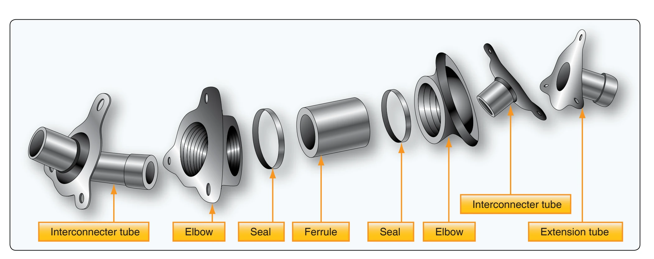
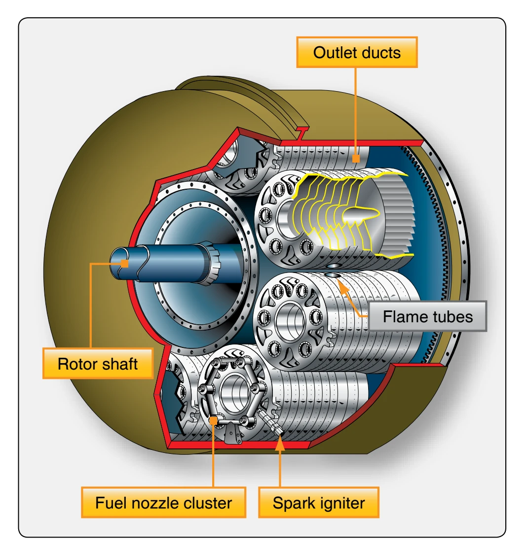
The burners are interconnected by projecting flame tubes which facilitate the engine-starting process as mentioned previously in the can-type combustion chamber familiarization. The flame tubes function identically to those previously discussed, differing only in construction details.
The can-annular combustion chamber is not used in modern
engines. The forward face of each chamber presents six apertures, which align with the six fuel nozzles of the corresponding fuel nozzle cluster. [Figure 1-56] These nozzles are the dual-orifice (duplex) type requiring the use of a flow-divider (pressurizing valve), as mentioned in the can-type combustion chamber discussion. Around each nozzle are preswirl vanes for imparting a swirling motion to the fuel spray, which results in better atomization of the fuel, better burning, and efficiency. The swirl vanes function to provide two effects imperative to proper flame propagation:
- High flame speed—better mixing of air and fuel, ensuring spontaneous burning.
- Low air velocity axially—swirling eliminates overly rapid flame movement axially.
The swirl vanes greatly aid flame propagation, since a high degree of turbulence in the early combustion and cooling stages is desirable. The vigorous mechanical mixing of the fuel vapor with the primary air is necessary, since mixing by diffusion alone is too slow. This same mechanical mixing is also established by other means, such as placing coarse
screens in the diffuser outlet, as is the case in most axialflow engines.
The can-annular combustion chambers also must have the required fuel drain valves located in two or more of the bottom chambers, assuring proper drainage and elimination of residual fuel burning at the next start.
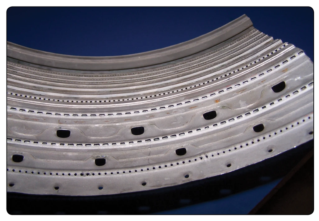
The flow of air through the holes and louvers of the canannular chambers, is almost identical with the flow through other types of burners. [Figure 1-56] Special baffling is used to swirl the combustion airflow and to give it turbulence. Figure 1-57 shows the flow of combustion air, metal cooling air, and the diluent or gas cooling air. The air flow direction
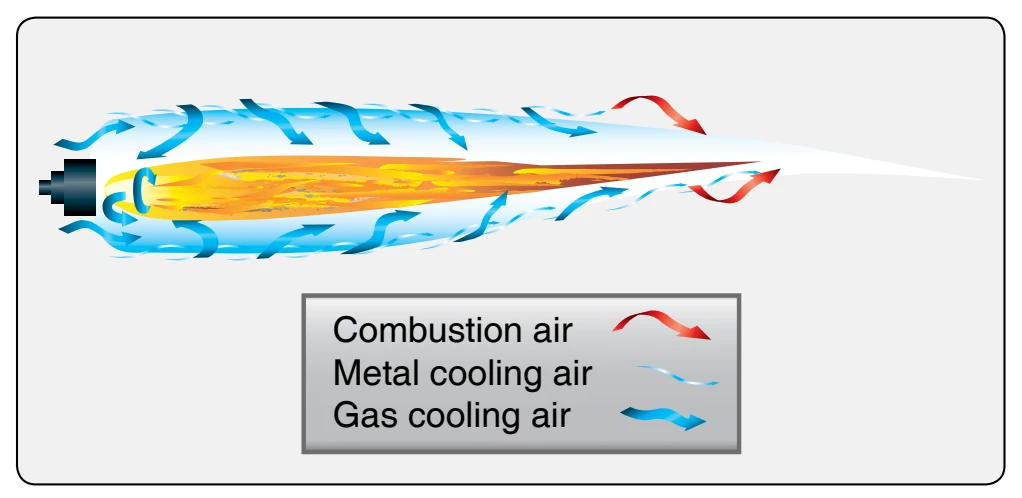
is indicated by the arrows.
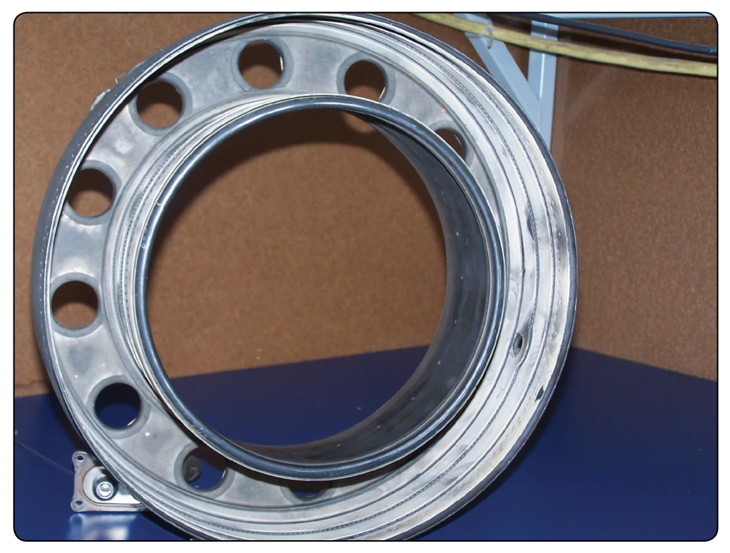
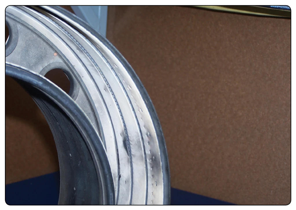
The basic components of an annular combustion chamber are a housing and a liner, as in the can type. The liner consists of an undivided circular shroud extending all the way around the outside of the turbine shaft housing. The chamber is constructed of heat-resistant materials, which are sometimes coated with thermal barrier materials, such as ceramic materials. The annular combustion chamber is illustrated in Figure 1-58. Modern turbine engines usually have an annular combustion chamber. As can be seen in Figure 1-59, the annular combustion chamber also uses louvers and holes to prevent the flame from contacting the side of the combustion chamber.
A reverse-flow combustor is a type of combustor in which the air from the compressor enters the combustor outer case and reverses its direction as it flows into the inner liner. It again reverses its direction before it flows through the turbine. Reverse-flow combustors are used where engine length is critical.
Turbine Section
The turbine transforms a portion of the kinetic (velocity) energy of the exhaust gases into mechanical energy to drive the gas generator compressor and accessories. The sole purpose of the gas generator turbine is to absorb approximately 60 to 70 percent of the total pressure energy from the exhaust gases. The exact amount of energy absorption at the turbine is determined by the load the turbine is driving (i.e., compressor size and type, number of accessories, and the load applied by the other turbine stages). These turbine stages can be used to drive a low-pressure compressor (fan), propeller, and shaft. The turbine section of a gas turbine engine is located aft, or downstream, of the combustion chamber. Specifically, it is directly behind the combustion chamber outlet.
The turbine assembly consists of two basic elements: turbine inlet guide vanes and turbine disc. [Figures 1-60 and 1-61] The stator element is known by a variety of names, of which turbine inlet nozzle vanes, turbine inlet guide vanes, and nozzle diaphragm are three of the most commonly used.