
Chapter 10
Engine Maintenance & Operation

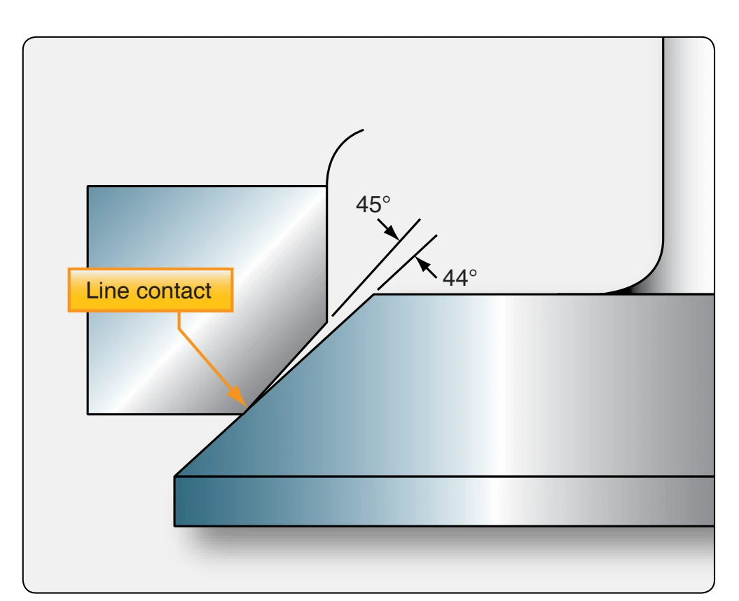
The interference fit is used to obtain a more positive seal by means of a narrow contact surface. [Figure 10-23] Theoretically, there is a line contact between the valve and seat. With this line contact, the load that the valve exerts against the seat is concentrated in a very small area, thereby increasing the unit load at any one spot. The interference fit is especially beneficial during the first few hours of operation after an overhaul. The positive seal reduces the possibility of a burned valve or seat that a leaking valve might produce. After the first few hours of running, these angles tend to pound down and become identical.
Notice that the interference angle is ground into the valve, not the seat. It is easier to change the angle of the valve grinder work head than to change the angle of a valve seat grinder stone. Do not use an interference fit unless the manufacturer approves it.
Install the valve into the chuck and adjust the chuck so that the valve face is approximately 2 inches from the chuck. [Figure 10-24] If the valve is chucked any further out, there is danger of excessive wobble and also a possibility of grinding into the stem.
There are various types of valve grinding machines. In one type, the stone is moved across the valve face; in another, the valve is moved across the stone. Whichever type is used, the following procedures are typical of those performed when refacing a valve.
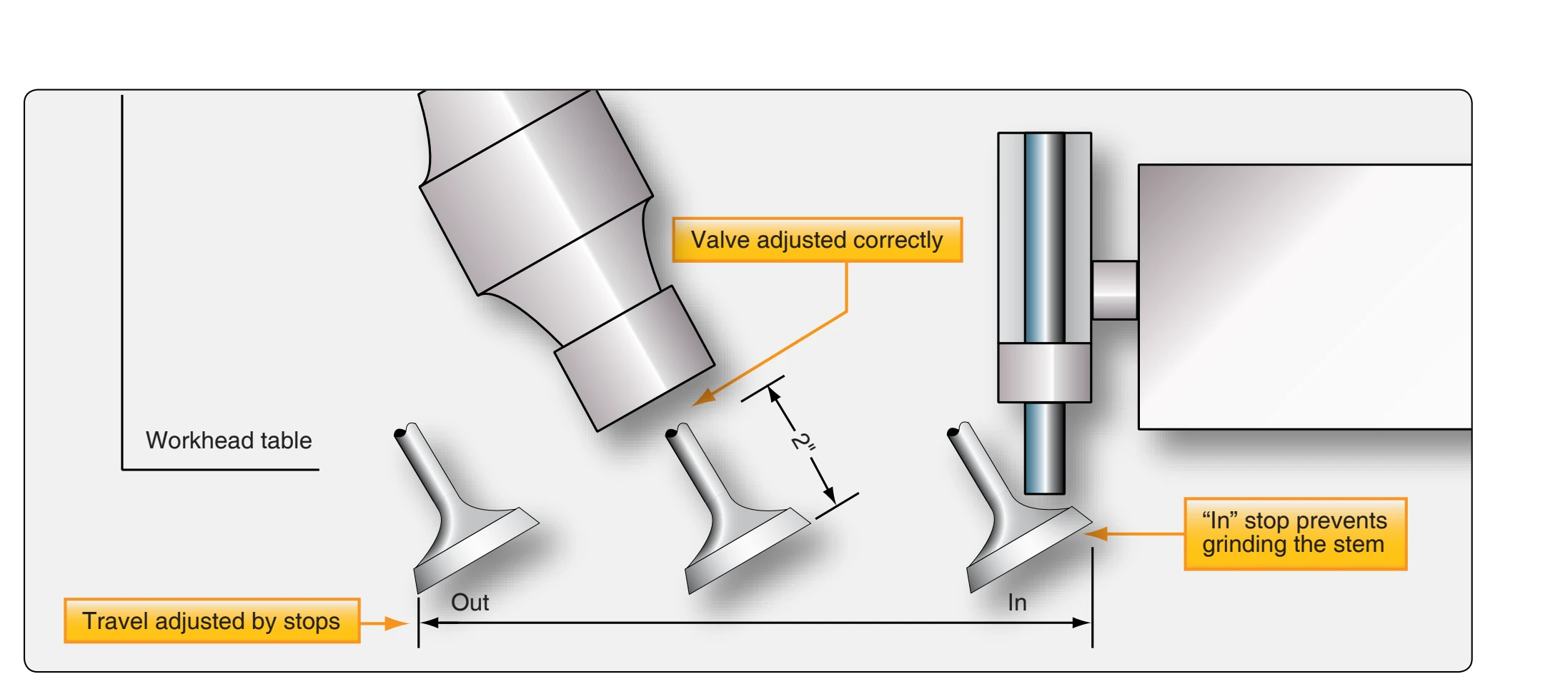
Check the travel of the valve face across the stone. The valve should completely pass the stone on both sides, yet not travel far enough to grind the stem. There are stops on the machine that can be set to control this travel.
With the valve set correctly in place, turn on the machine and the grinding fluid so that it splashes on the valve face. Back the grinding wheel off all the way. Place the valve directly in front of the stone. [Figure 10-25] Slowly bring the wheel forward until a light cut is made on the valve. The intensity of the grind is measured by sound more than anything else. Slowly draw the valve back and forth across the stone without increasing the cut. Move the work head table back and forth using the full face of the stone, but always keep the valve face on the stone. When the sound of the grind diminishes, indicating that some valve material has been removed, move the workhead table to the extreme left to stop rotation of the valve. Inspect the valve to determine if further grinding is necessary. If another cut must be made, bring the valve in
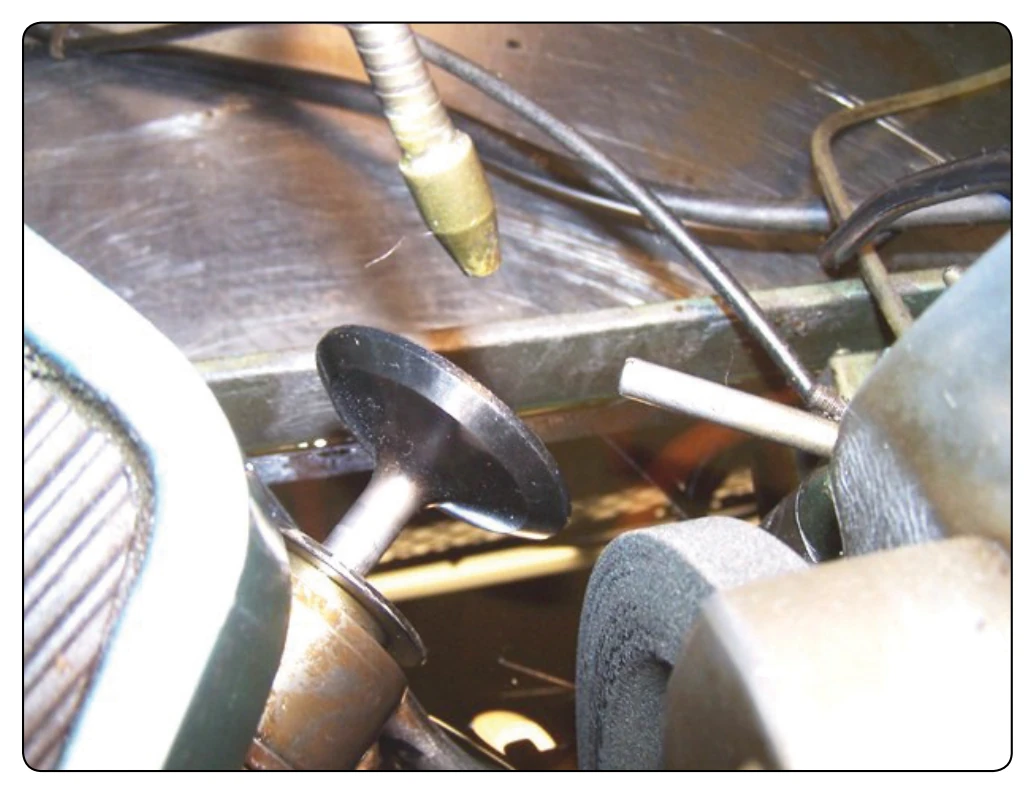
front of the stone, then advance the stone out to the valve. Do not increase the cut without having the valve directly in front of the stone.
An important precaution in valve grinding, as in any kind of grinding, is to make light cuts only. Heavy cuts cause chattering, that may make the valve surface so rough that much time is lost in obtaining the desired finish.
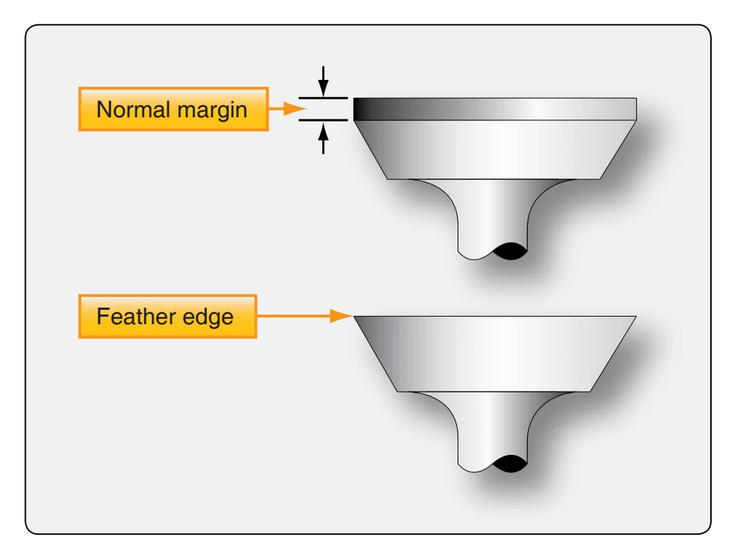
After grinding, check the valve margin to be sure that the valve edge has not been ground too thin. A thin edge is called a feather edge and can lead to pre-ignition; the valve edge would burn away in a short period of time, and the cylinder would have to be overhauled again. Figure 10-26 shows a valve with a normal margin and one with a feather edge.
The valve tip may be resurfaced on the valve grinder. The tip is ground to remove cupping or wear, and also to adjust valve clearances on some engines.
The valve is held by a clamp on the side of the stone. [Figure 10-27] With the machine and grinding fluid turned on, the valve is pushed lightly against the stone and swung back and forth. Do not swing the valve stem off either edge of the stone. Because of the tendency for the valve to overheat during this grinding, be sure plenty of grinding fluid covers the tip.
Grinding of the valve tip may remove, or partially remove, the bevel on the edge of the valve. To restore this bevel, mount a V-way approximately 45° to the grinding stone. Hold the valve onto the V-way and twist the valve tip onto the stone. With a light touch, grind all the way around the tip. This bevel prevents scratching the valve guide when the valve is installed.
Valve Lapping & Leak Testing
After the grinding procedure is finished, it is sometimes necessary that the valve be lapped to the seat. This is done by applying a small amount of lapping compound to the valve face, inserting the valve into the guide, and rotating the valve with a lapping tool until a smooth, gray finish appears at the contact area. The appearance of a correctly lapped valve is shown in Figure 10-28.