
Chapter 10
Engine Maintenance & Operation
Engine instruments can operate using different methods, some mechanically, some electrically, and some by sensing
the direct pressure of air or liquid. Some of the basic instruments are:
- Carburetor air temperature gauge.
- Fuel pressure gauge.
- Fuel-flow meter.
- Manifold pressure gauge.
- Oil temperature gauge.
- Oil pressure gauge.
- Tachometer.
- Exhaust gas temperature gauge.
- Cylinder head temperature gauge.
- Torquemeter.
Instrument markings, ranges of operation, minimum and maximum limits, and the interpretation of these markings are general to all the instruments. Generally, the instrument marking system consists of three colors: red, yellow, and green. A red line, or mark, indicates a point beyond which a dangerous operating condition exists. A red arc indicates a dangerous operating range due generally to an engine propeller vibration range. This arc can be passed through, but the engine cannot be operated in this area. Of the two, the red mark is used more commonly and is located radially on the cover glass or dial face. The yellow arc covers a given range of operation and is an indication of caution. Generally, the yellow arc is located on the outer circumference of the instrument cover glass or dial face. The green arc shows a normal and safe range of operation. When the markings appear on the cover glass, a white line is used as an index mark, often called a slippage mark. The white radial mark indicates any movement between the cover glass and the case, a condition that would cause mislocation of the other range and limit markings.
Carburetor Air Temperature (CAT) Indicator
Measured at the carburetor entrance, carburetor air temperature (CAT) is regarded by many as an indication of induction system ice formation. Although it serves this purpose, it also provides many other important items of information.
The powerplant is a heat machine, and the temperature of its components, or the fluids flowing through it, affects the combustion process either directly or indirectly. The temperature level of the induction air affects not only the charge density, but also the vaporization of the fuel. CAT is also useful for checking induction system condition. Backfiring is indicated as a momentary rise on the gauge, provided it is of sufficient severity for the heat to be sensed at the carburetor air-measuring point. A sustained induction system fire shows a continuous increase of CAT.
The CAT should be noted before starting and just after shutdown. The temperature before starting is the best indication of the temperature of the fuel in the carburetor body and tells whether vaporization is sufficient for the initial firing, or whether the mixture must be augmented by priming. If an engine has been shut down for only a short time, the residual heat in the carburetor may make it possible to rely on the vaporizing heat in the fuel and powerplant. Priming would then be unnecessary.
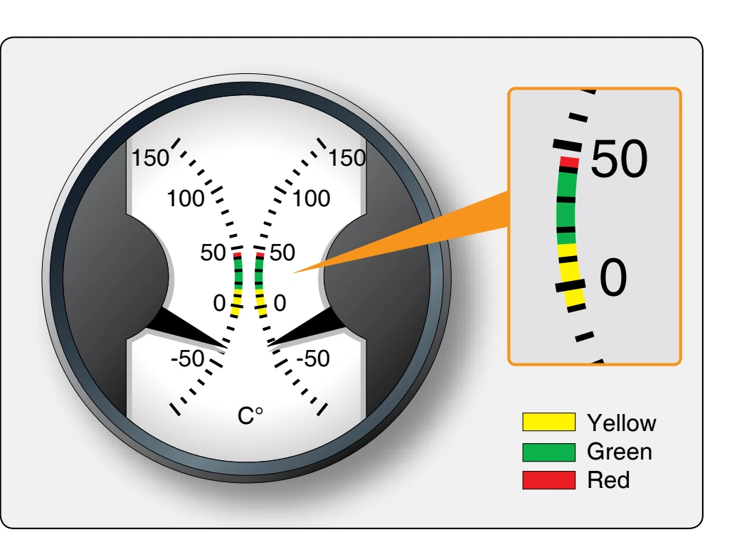
After shutdown, a high CAT is a warning that the fuel trapped in the carburetor will expand, producing high internal pressure. When a high temperature is present at this time, the fuel line and manifold valves should be open so that the pressure can be relieved by allowing fuel passage back to the tank. The CAT gauge indicates the temperature of the air before it enters the carburetor. The temperature reading is sensed by a bulb or electric sensor. In the test cell, the sensor is located in the air intake passage to the engine and, in an aircraft, it is located in the ram-air intake duct. The CAT gauge is calibrated in the centigrade scale. [Figure 10-35] This gauge, like many other multi-engine aircraft instruments, is a dual gauge; two gauges, each with a separate pointer and scale, are used in the same case.
Notice the range markings used. The yellow arc indicates a range from –10 °C to +15 °C, since the danger of icing occurs between these temperatures. The green range indicates the normal operating range from +15 °C to +40 °C. The red line indicates the maximum operating temperature of 40 °C; any operation at a temperature over this value places the engine in danger of detonation.
Fuel Pressure Indicator
The fuel pressure gauge is calibrated in pounds per square inch (psi) of pressure. It is used during the test run-in to measure engine fuel pressure at the carburetor inlet, the fuel
feed valve discharge nozzle, and the main fuel supply line. Fuel gauges are located in the operator’s control room and are connected by flexible lines to the different points at which pressure readings are desired during the testing procedures.
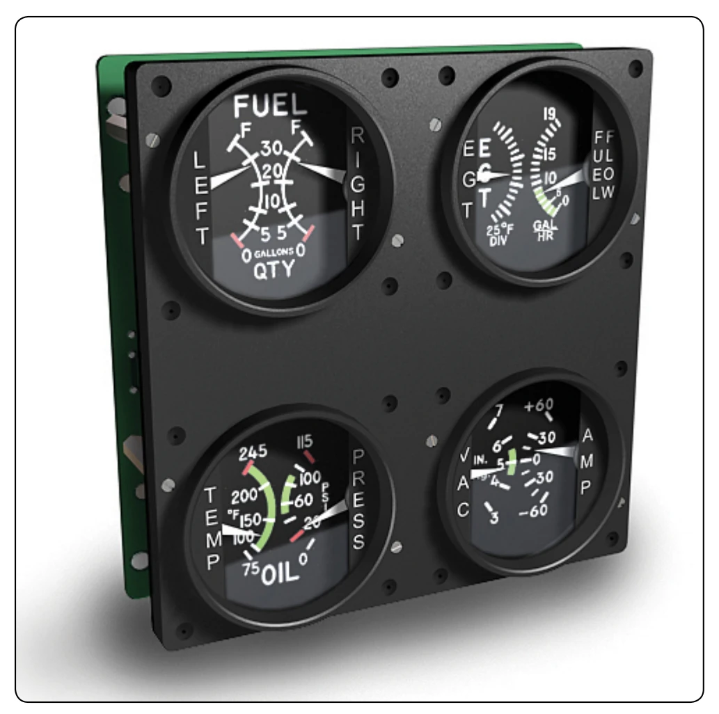
In some aircraft installations, the fuel pressure is sensed at the carburetor or fuel injection unit inlet of each engine, and the pressure is indicated on individual gauges on the instrument panel. [Figure 10-36] The dial is calibrated in graduations and is extended and numbered. The numbers range from 0 to 10 in this example. The red line on the dial at the 2 pounds psi graduation shows the minimum fuel pressure allowed during flight. The green arc shows the desired range of operation, which is 2 to 9 psi. The red line at the 9 psi graduation indicates the maximum allowable fuel pressure. Fuel pressures vary with the type of fuel system installation and the size of the engine. When fuel injection systems are used, the fuel pressure range is much higher; the minimum allowable pressure is approximately 10 psi, and the maximum is generally 25 psi.
Oil Pressure Indicator
The main oil pressure reading is taken at the pressure side of the oil pump. Generally, there is only one oil pressure gauge for each aircraft engine. The oil pressure gauge dial does not show the pressure range or limits for all installations. [Figure 10-36] The actual markings for specific aircraft may be found in the aircraft specifications or Type Certificate Data Sheets. The lower red line at 25 psi indicates the minimum oil pressure permissible in flight. The green arc between 60 to 85 psi illustrates the desired operating oil pressure range. The red line at 100 psi indicates maximum permissible oil pressure.
The oil pressure gauge indicates the pressure, in psi, that the oil of the lubricating system is being supplied to the moving parts of the engine. The engine should be shut down immediately if the gauge fails to register pressure when the engine is operating. Excessive oscillation of the gauge pointer indicates that there is air in the lines leading to the gauge, or that some unit of the oil system is functioning improperly.