
Chapter 10
Engine Maintenance & Operation
Oil Temperature Indicator
During engine run-in in the test cell, engine oil temperature readings are taken at the oil inlet and outlet. From these readings, it can be determined if the engine heat transferred to the oil is low, normal, or excessive. This information is of extreme importance during the breaking-in process of large reciprocating engines. The oil temperature gauge line in the aircraft is connected at the oil inlet to the engine.
Three range markings are used on the oil temperature gauge. The green arc in Figure 10-36, on the dial, shows the minimum oil temperature permissible for ground operational checks or during flight. The green mark between 25 °F and below 245 °F shows the desired oil temperature for continuous engine operation. The red mark at 245 °F indicates the maximum permissible oil temperature.
Fuel-Flow Meter
The fuel-flow meter measures the amount of fuel delivered to the engine. During engine testing procedures, the fuel-flow to the engine can be measured by three different methods: a direct flow meter, a pressure-based flow meter, or a turbine sensor-based flow meter. The direct reading flow meter uses a series of calibrated tubes located in the control room. The tubes are of various sizes to indicate different volumes of fuel-flow. Each tube contains a float that can be seen by the operator, and as the fuel-flow through the tube varies, the float is either raised or lowered, indicating the amount of fuel-flow. From these indications, the operator can determine whether an engine is operating at the correct air-fuel mixture for a given power setting. Reciprocating engines on light aircraft usually use a fuel pressure gauge that is also used for the flow meter. This is because the fuel-flow is proportional to the fuel pressure in this system. Fuel-flow is normally measured in gallons per hour.
In most turbine aircraft installations, the fuel-flow indicating system consists of a transmitter and an indicator for each engine. The fuel-flow transmitter is conveniently mounted in the engine’s accessory section and measures the fuel-flow between the engine-driven fuel pump and the fuel control device. The transmitter is an electrical device that contains a turbine that turns faster as the flow increases, which increases the electrical signal to the indicator. The fuel-flow transmitter is connected electrically to the indicator located on the aircraft flight deck, or on the test cell operator’s panel. The reading on the indicator on turbine aircraft is calibrated to record the amount of fuel-flow in pounds of fuel per hour.
Manifold Pressure Indicator
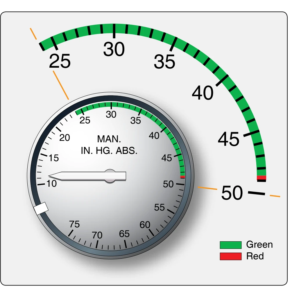
The preferred type of instrument for measuring the manifold pressure on reciprocating engines is a gauge that records the pressure as an absolute pressure reading. Absolute pressure1 takes into account the atmospheric pressure plus the pressure in the intake manifold. To read the manifold pressure of the engines, a specially designed manifold pressure gauge that indicates absolute manifold pressure in inches of mercury ("Hg) is used. The red line indicates the maximum manifold pressure permissible during takeoff.
The manifold pressure gauge range markings and indications vary with different kinds of engines and installations. Figure 10-37 illustrates the dial of a typical manifold pressure gauge and shows how the range markings are positioned. The green arc starts at 35 "Hg and continues to the 44 "Hg. The red line on the gauge, at 49 "Hg shows the manifold pressure recommended for takeoff. This pressure should not be exceeded.
Tachometer Indicator
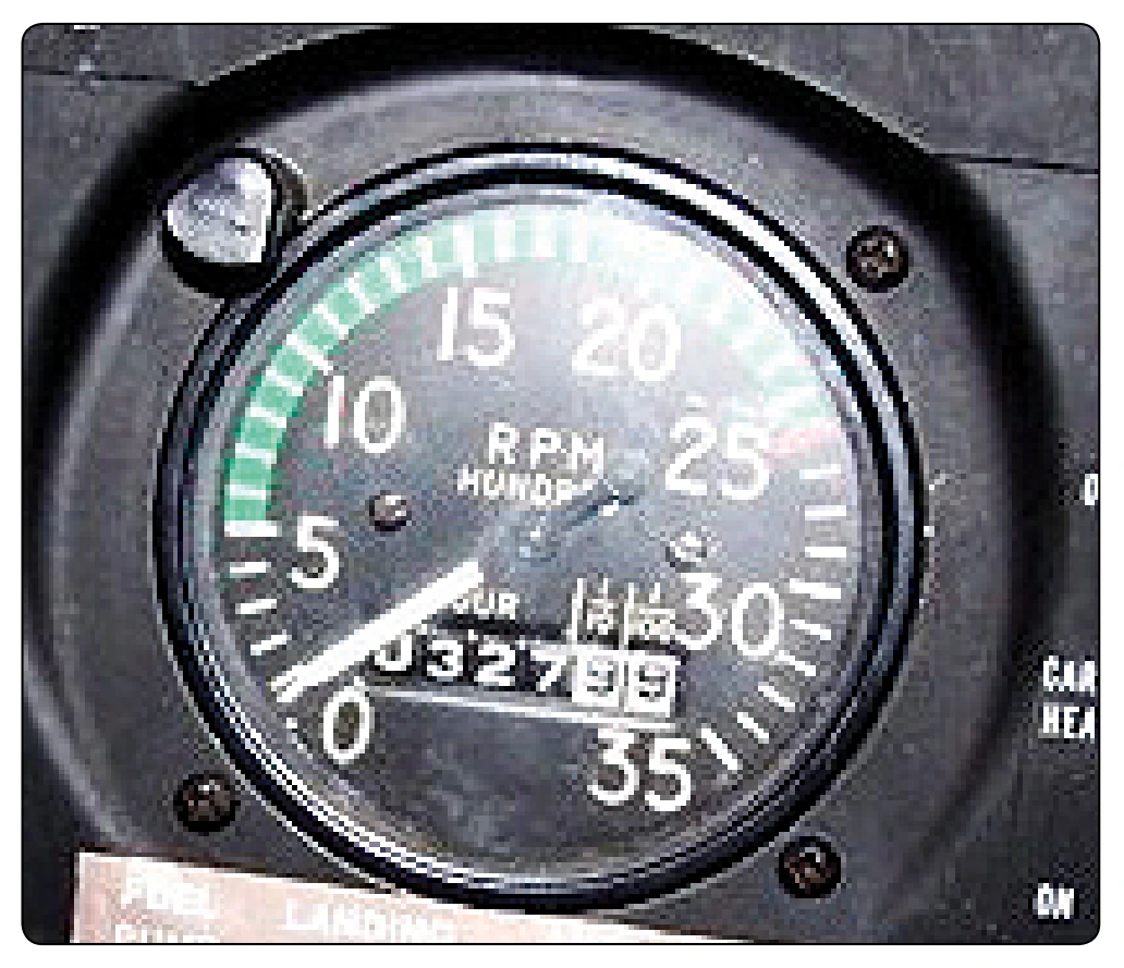
The tachometer for reciprocating engines shows the engine crankshaft rpm. The system used for testing the engine is the same as the system in the aircraft installation. The tachometer, often referred to as TACH, is calibrated in hundreds with graduations at every 100-rpm interval. The dial shown in Figure 10-38 starts at 0 rpm and goes to 35 (3,500 rpm). The green arc indicates the rpm range within operation that is permissible. The red line indicates the maximum rpm permissible during takeoff; any rpm beyond this value is an overspeed condition.
Turbine engines use percent rpm indicators due to the high rpm that the engines generally operate. Each rotating assembly in an engine has its own percent rpm indicator. The tachometer indicates speed of the compressor section. The 100 percent position on the indicator is the highest rpm at which the engine can operate. Red lines and green arcs operate the same as with reciprocating engines. Rotorcraft use two synchronous tachometers.
Cylinder Head Temperature Indicator
During the engine test procedures, the cylinder head temperatures of various cylinders on the reciprocating engine are normally tested. Thermocouples are connected to several cylinders and, by a selector switch, any cylinder head temperature can be indicated on the indicators. When installed in the aircraft, there is sometimes only one
thermocouple lead and indicator for each engine installed in an aircraft.
Cylinder head temperatures are indicated by a gauge connected to a thermocouple attached to the cylinder, that tests show to be the hottest on an engine in a particular installation. The thermocouple may be placed in a special gasket located under a rear spark plug, or in a special well in the top or rear of the cylinder head.
The temperature recorded at either of these points is merely a reference or control temperature; but as long as it is kept within the prescribed limits, the temperatures inside the cylinder dome, exhaust valve, and piston is within a satisfactory range. Since the thermocouple is attached to only one cylinder, it can do no more than give evidence of general engine temperature. While normally it can be assumed that the remaining cylinder temperatures are lower, conditions such as detonation are not indicated unless they occur in the cylinder that has the thermocouple attached.
The cylinder head temperature gauge range marking is similar to that of the manifold pressure and tachometer indicator. The cylinder head temperature gauge is a dual gauge that incorporates two separate temperature scales. [Figure 10-39] The scales are calibrated in increments of 10°, with numerals at the 0°, 100°, 200°, and 300° graduations. The space between any two graduation marks represents 10 °C. The blue arc on the gauge indicates the range within which operation is permitted in auto-lean. The bottom of this arc, 100 °C, indicates the minimum desired temperature to ensure efficient engine operation during flight. The top of the blue arc, 230 °C, indicates the temperature at which the mixture control must be moved to the “auto-rich” position. The green arc describes the range within which operation must be in auto-rich. The top of this arc, 248 °C, indicates maximum continuous power; all operation above this temperature is limited in time (usually 5 to 15 minutes). The red line indicates maximum permissible temperature, 260 °C.