
Chapter 11
Light-Sport Aircraft Engines
Electric System
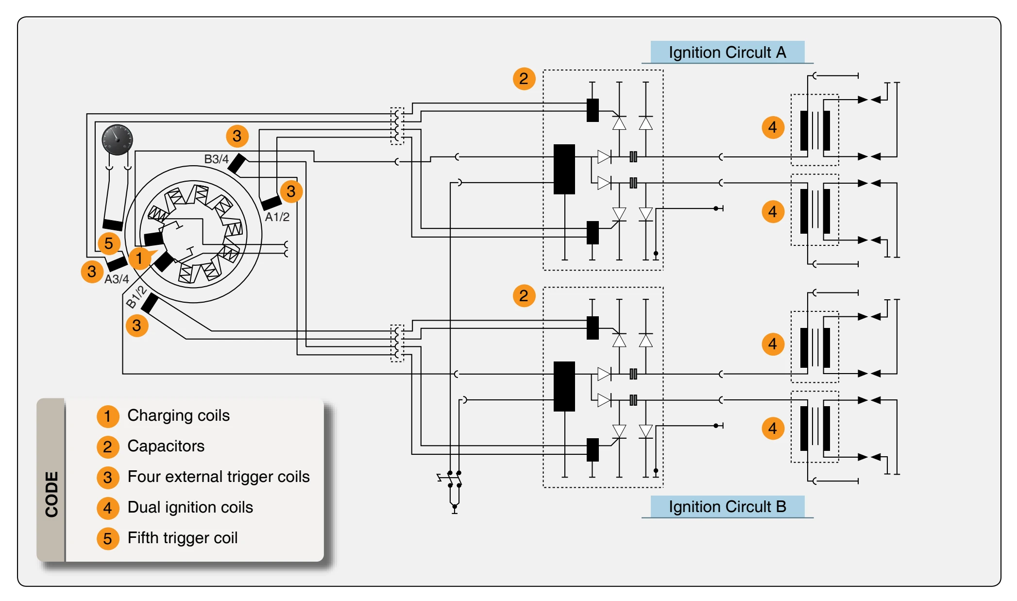
The Rotax 914 engine is equipped with a dual ignition unit that uses a breakerless, capacitor discharge design with an integrated generator. [Figure 11-11] The ignition unit is completely free of maintenance and needs no external power supply. Two independent charging coils (1) located on the generator stator supply one ignition circuit each. The energy is stored in capacitors of the electronic modules (2). At the moment of ignition, two each of the four external trigger coils (3) actuate the discharge of the capacitors via the primary circuit of the dual ignition coils (4). The firing order is as follows: 1-4-2-3. The fifth trigger coil (5) is used to provide the revolution counter signal.
Turbocharger & Control System
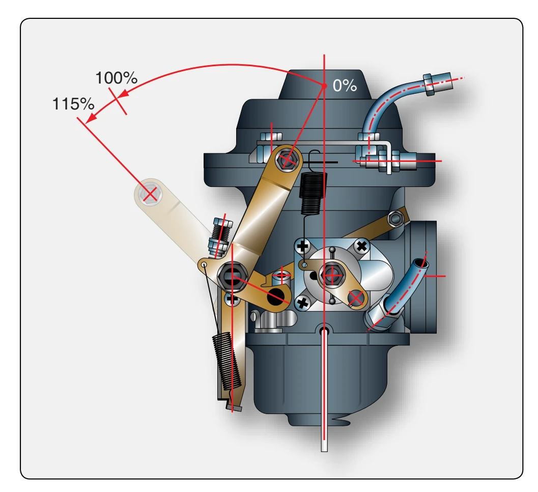
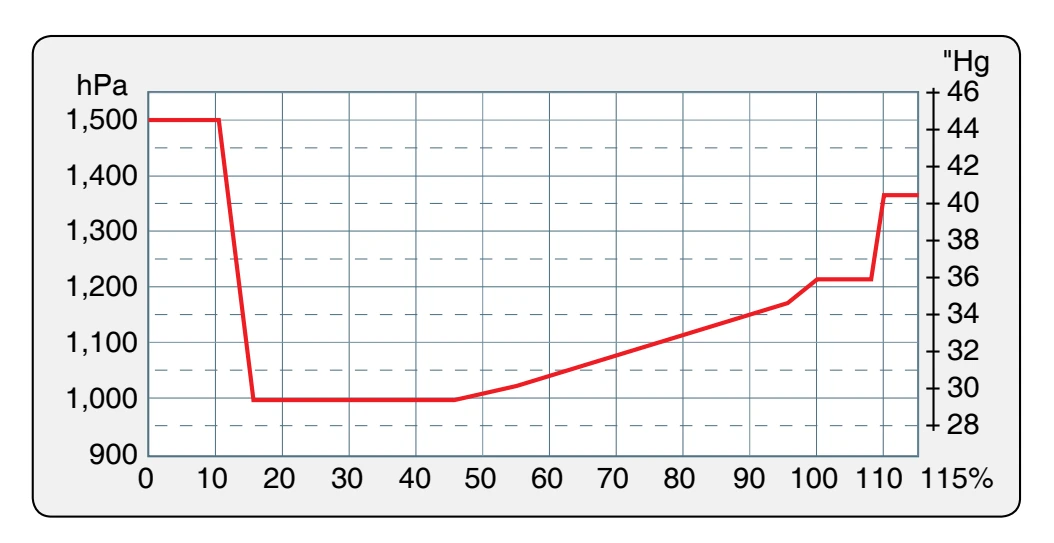
The Rotax 914 engine is equipped with an exhaust gas turbocharger making use of the energy in the exhaust gas for compression of the intake air or for providing boost pressure to the induction system. The boost pressure in the induction system (airbox) is controlled by means of an electronically controlled valve (wastegate) in the exhaust gas turbine. The wastegate regulates the speed of the turbocharger and consequently the boost pressure in the induction system. The required nominal boost pressure in the induction system is determined by the throttle position sensor mounted on the carburetor 2/4. The sensor’s transmitted position is linear from 0 to 115 percent, corresponding to a throttle position from idle to full power. [Figure 11-12] For correlation between throttle position and nominal boost pressure in the induction, refer to Figure 11-13. As shown in the diagram, with the throttle position at 108–110 percent results in a rapid rise of nominal boost pressure.
To avoid unstable boost, the throttle should be moved smoothly through this area either to full power (115 percent) or at a reduced power setting to maximum continuous power. In this range (108–110 percent throttle position), small changes in throttle position have a big effect on engine performance and speed. These changes are not apparent to the pilot from the throttle lever position. The exact setting for a specific performance is virtually impossible in this range and has to be prevented, as it might cause control fluctuations or surging. Besides the throttle position, overspeeding of the engine and too high intake air temperature have an effect on the nominal boost pressure. If one of the stated factors exceeds the specified limits, the boost pressure is automatically reduced, thus protecting the engine against over boost and detonation.
The turbo control unit (TCU) is furnished with output connections for an external red boost lamp and an orange
and illuminates the red boost lamp continuously. The TCU registers the time of full throttle operation (boost pressure). Full throttle operation for longer than 5 minutes, with the red boost light illuminated, makes the red boost lamp start blinking. The red boost lamp helps the pilot to avoid full power operation for longer than 5 minutes or the engine could be subject to thermal and mechanical overstress.
HKS 700T Engine
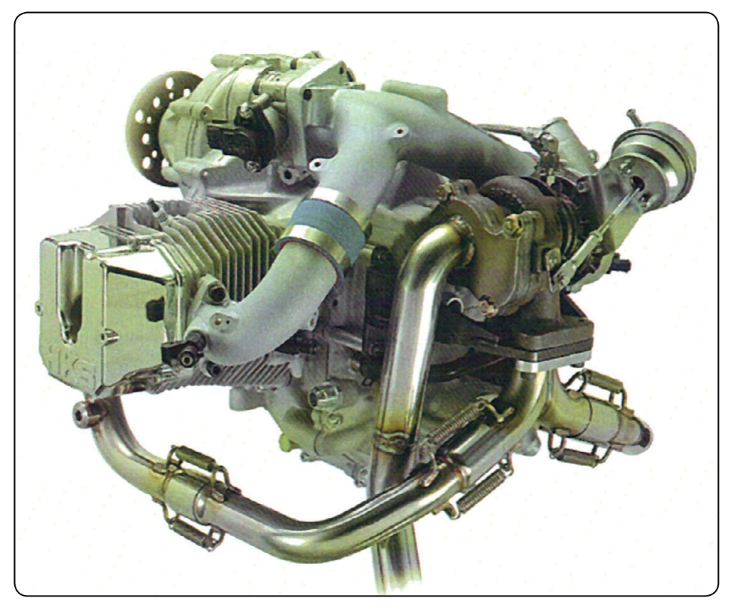
The HKS 700T engine is a four-stroke, two cylinder turbocharged engine equipped with an intercooler. [Figure 11-14] The horizontally opposed cylinders house four valves per cylinder, with a piston displacement of 709
- It uses an electronic control fuel injection system. A reduction gearbox is used to drive the propeller flange at a speed reduction ratio of 2.13 to
- The engine is rated at 77 horsepower continuous and 80 horsepower takeoff (3 minutes) at 4,900 rpm and 5,300 rpm, respectively. A total engine weight of 126 pounds provides a good power to weight ratio. The 700T has a TBO of 500 hours.
Jabiru Light-Sport Engines
Jabiru engines are designed to be manufactured using the latest manufacturing techniques. [Figure 11-15] All Jabiru engines are manufactured, assembled, and ran on a Dynometer, then calibrated before delivery. The crankcase halves, cylinder heads, crankshaft, starter motor housings, gearbox cover (the gearbox powers the distributor rotors), together with many smaller components are machined from solid material. The sump (oil pan) is the only casting. The cylinders are machined from bar 4140 chrome molybdenum alloy steel, with the pistons running directly in the steel bores. The crankshaft is also machined from 4140 chrome molybdenum alloy steel, the journals of which are precision ground prior to being Magnaflux inspected. The camshaft is manufactured from 4140 chrome molybdenum alloy steel with nitrided journals and cams.
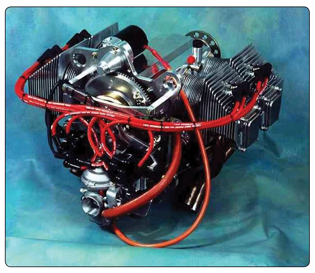
The propeller is direct crankshaft driven and does not use a reduction gearbox. This facilitates its lightweight design and keeps maintenance costs to a minimum. The crankshaft features a removable propeller flange that enables the easy replacement of the front crankshaft seal and provides for a propeller shaft extension to be fitted, should this be required for particular applications. Cylinder heads are machined from a solid aluminum billet that is purchased directly from one company, thereby providing a substantive quality control trail to the material source. Connecting rods are machined from 4140 alloy steel and the 45 millimeters big end bearings are of the automotive slipper type. The ignition coils are sourced from outside suppliers and are modified by Jabiru for their own particular application.
An integral alternator provides AC rectification for battery charging and electrical accessories. The alternator is attached to the flywheel and is driven directly by the crankshaft. The ignition system is a transistorized electronic system; two fixed coils mounted adjacent to the flywheel are energized by magnets attached to the flywheel. The passing of the coils by the magnets creates the high voltage current, that is transmitted by high tension leads to the center post of two automotive type distributors, which are simply rotors and caps, before distribution to automotive spark plugs (two in the top of each cylinder head). The ignition system is fixed timing and, therefore, removes the need for timing adjustment. It is suppressed to prevent radio interference.