Chapter 11
Light-Sport Aircraft Engines
Many certificated engines are used with light-sport and experimental aircraft. Generally, cost is a big factor when considering this type of powerplant. The certificated engines tend to be much more costly than the non-certificated engines, and are not ASTM approved.
Rotax 912/914
Figure 11-6 shows a typical four cylinder, four-stroke Rotax horizontally opposed engine. The opposed-type engine has
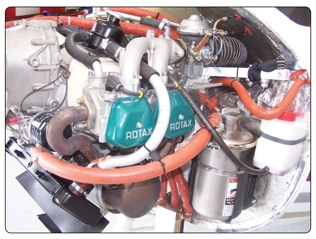
two banks of cylinders directly opposite each other with a crankshaft in the center. The pistons of both cylinder banks are connected to the single crankshaft. The engine cylinder heads are both liquid-cooled and air-cooled; the air-cooling is mostly used on the cylinder. It is generally mounted with the cylinders in a horizontal position. The opposed-type engine has a low weight to horsepower ratio, and its narrow silhouette makes it ideal for horizontal installation on the aircraft wings (twin-engine applications). Another advantage is its low vibration characteristics. It is an ideal replacement for the Rotax 582 two-cylinder, two-stroke engine, which powers many of the existing light aircraft, as it is the same weight as the Rotax 582. These engines are ASTM approved for installation into light-sport category aircraft, with some models being FAA-certificated engines.
Description of Systems
Cooling System
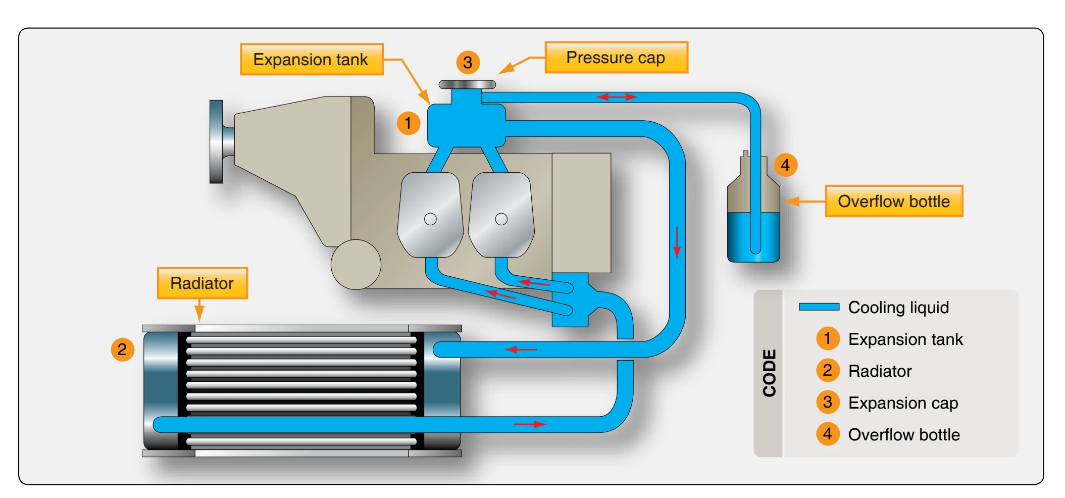
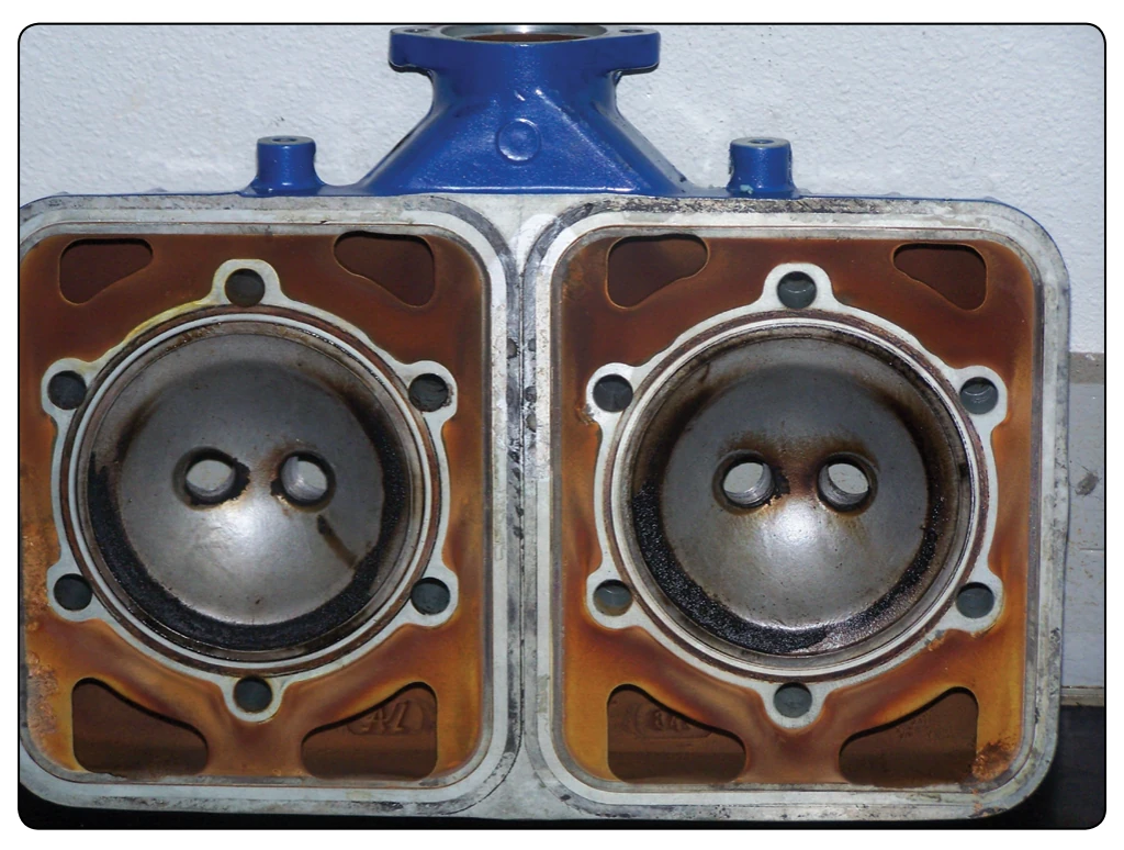
The cooling system of the Rotax 914, shown in Figure 11-7, is designed for liquid cooling of the cylinder heads and ram-air cooling of the cylinders. The cooling system of the cylinder heads is a closed circuit with an expansion tank. [Figure 11-8] The coolant flow is forced by a water pump driven from the camshaft, from the radiator, to the cylinder heads. From the top of the cylinder heads, the coolant passes on to the expansion tank (1). Since the standard location of the radiator (2) is below engine level, the expansion tank located on top of the engine allows for coolant expansion.
The expansion tank is closed by a pressure cap (3) (with excess pressure valve and return valve). As the temperature of the coolant rises, the excess pressure valve opens and the coolant flows via a hose at atmospheric pressure to the transparent overflow bottle (4). When cooling down, the coolant is sucked back into the cooling circuit. Coolant temperatures are measured by means of temperature probes installed in the cylinder heads 2 and 3. The readings are taken on measuring the hottest point of cylinder head depending on engine installation. [Figure 11-7]
Fuel System
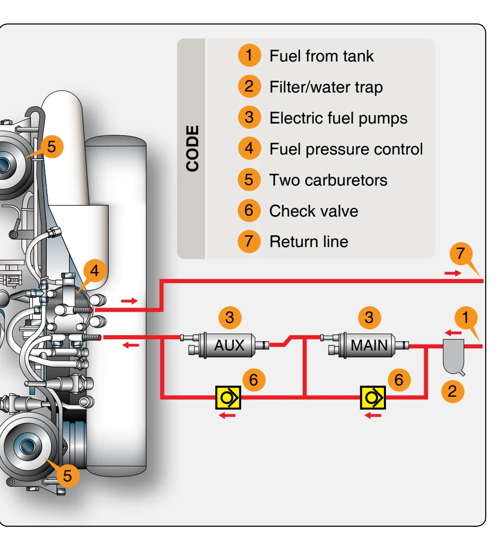
The fuel flows from the tank (1) via a coarse filter-water trap (2) to the two electric fuel pumps (3) connected in series. [Figure 11-9] From the pumps, fuel passes on via the fuel pressure control (4) to the two carburetors (5). Parallel to each fuel pump is a separate check valve (6) installed via the return line (7) that allows surplus fuel to flow back to the fuel tank. Inspection for possible constriction of diameter or
obstruction must be accomplished to avoid overflowing of fuel from the carburetors. The return line must not have any resistance to flow. The fuel pressure control ensures that the fuel pressure is always maintained approximately 0.25 bar (3.63 pounds per square inch (psi)) above the variable boost pressure in the airbox and thus, ensures proper operation of the carburetors.
Lubrication System
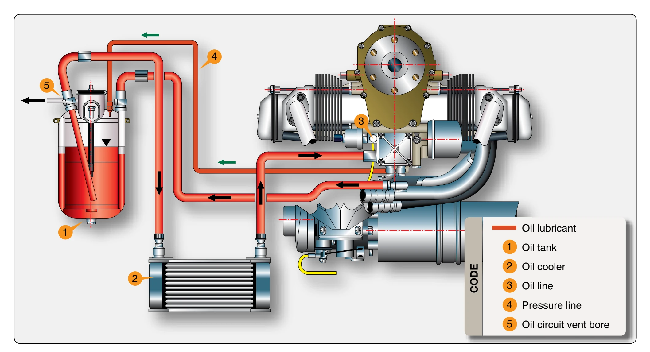
The Rotax 914 engine is provided with a dry, sump-forced lubrication system with a main oil pump with integrated pressure regulator and an additional suction pump. [Figure 11-10] The oil pumps are driven by the camshaft. The main oil pump draws oil from the oil tank (1) via the oil cooler (2) and forces it through the oil filter to the points of lubrication. It also lubricates the plain bearings of the
turbocharger and the propeller governor. The surplus oil emerging from the points of lubrication accumulates on the bottom of crankcase and is forced back to the oil tank by the blow-by gases. The turbocharger is lubricated via a separate oil line (from the main oil pump). The oil emerging from the lower placed turbocharger collects in the oil sump by a separate pump and is pumped back to the oil tank via the oil line (3). The oil circuit is vented via bore (5) in the oil tank. There is an oil temperature sensor in the oil pump flange for reading of the oil inlet temperature.