
Chapter 2
Engine Fuel & Fuel Metering Systems
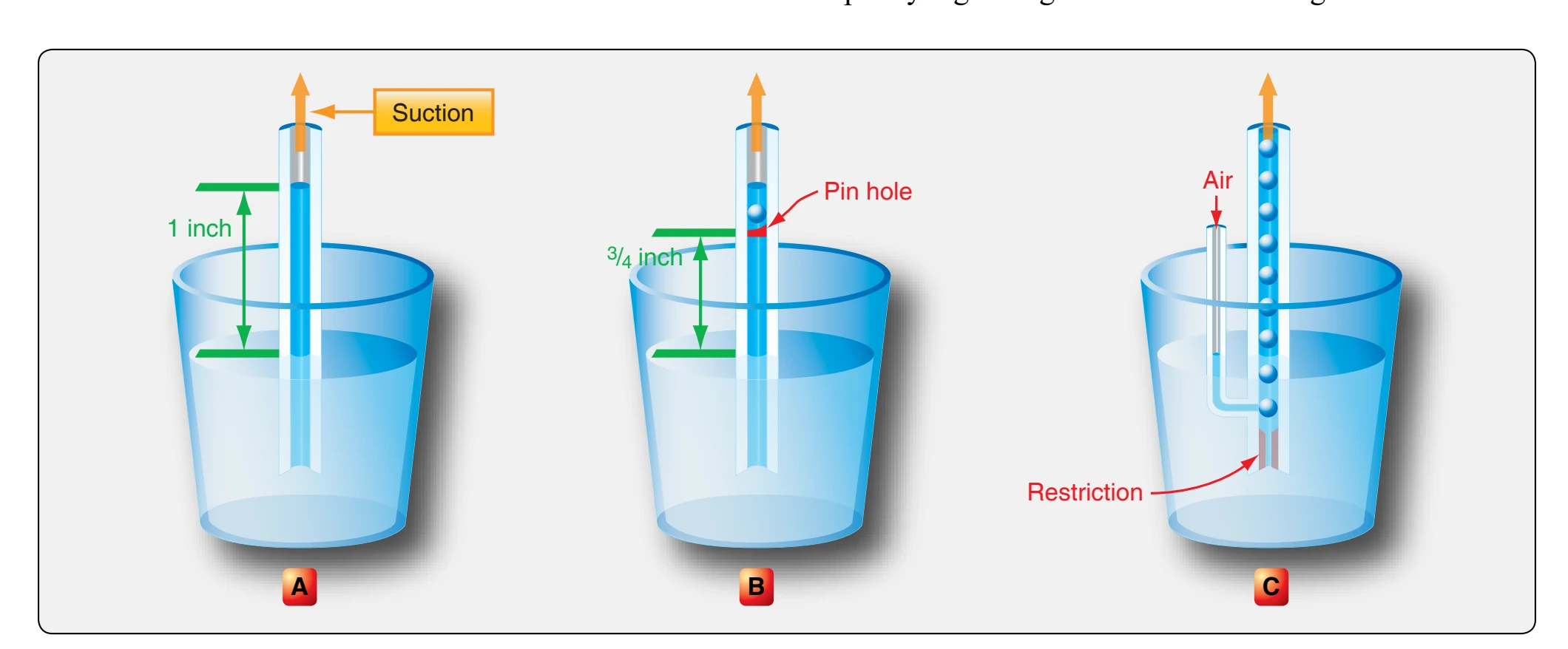
The basic principle of the air bleed can be explained by simple diagrams, as shown in Figure 2-13. In each case, the same degree of suction is applied to a vertical tube placed in the container of liquid. As shown in A, the suction applied on the upper end of the tube is sufficient to lift the liquid a distance of about 1 inch above the surface. If a small hole is made in the side of the tube above the surface of the liquid, as in B, and suction is applied, bubbles of air enter the tube and the liquid is drawn up in a continuous series of small slugs or drops. Thus, air “bleeds” into the tube and partially reduces the forces tending to retard the flow of liquid through the tube. However, the large opening at the bottom of the tube effectively prevents any great amount of suction from being exerted on the air bleed hole or vent. Similarly, an air bleed hole that is too large in proportion to the size of the tube would reduce the suction available to lift the liquid. If the system is modified by placing a metering orifice in the bottom of the tube and air is taken in below the fuel level by means of an air bleed tube, a finely divided mixture of air and liquid is formed in the tube, as shown in C.
In a carburetor, a small air bleed is bled into the fuel nozzle slightly below the fuel level. The open end of the air bleed is in the space behind the venturi wall where the air is relatively motionless and at approximately atmospheric pressure. The low pressure at the tip of the nozzle not only draws fuel from the float chamber but also draws air from behind the venturi. Air bled into the main metering fuel system decreases the fuel density and destroys surface tension. This results in better vaporization and control of fuel discharge, especially at lower engine speeds. The throttle, or butterfly valve, is located in the carburetor barrel near one end of the venturi. It provides a means of controlling engine speed or power
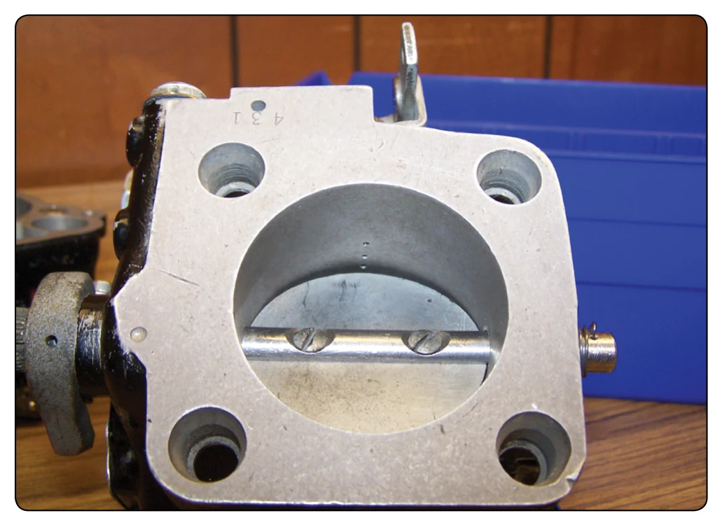
a disc that can rotate on an axis, so that it can be turned to open or close the carburetor air passage.
Idling System
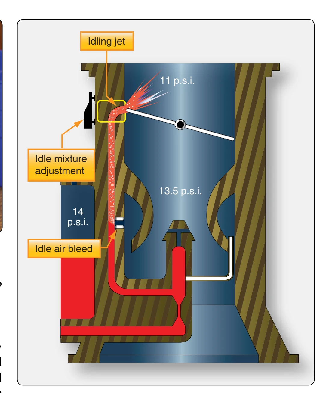
With the throttle valve closed at idling speeds, air velocity through the venturi is so low that it cannot draw enough fuel from the main discharge nozzle; in fact, the spray of fuel may stop altogether. However, low pressure (piston suction) exists on the engine side of the throttle valve. In order to allow the engine to idle, a fuel passageway is incorporated to discharge fuel from an opening in the low pressure area near the edge of the throttle valve. [Figure 2-14] This opening is called the idling jet. With the throttle open enough so that the main discharge nozzle is operating, fuel does not flow out of the idling jet. As soon as the throttle is closed far enough to stop the spray from the main discharge nozzle, fuel flows out the idling jet. A separate air bleed, known as the idle air bleed, is included as part of the idling system. It functions in the same manner as the main air bleed. An idle mixture adjusting device is also incorporated. A typical idling system is illustrated in Figure 2-15.
Mixture Control System
As altitude increases, the air becomes less dense. At an altitude of 18,000 feet, the air is only half as dense as it is at sea level. This means that a cubic foot of space contains only half as much air at 18,000 feet as at sea level. An engine cylinder full of air at 18,000 feet contains only half as much oxygen as a cylinder full of air at sea level.
The low pressure area created by the venturi is dependent upon air velocity rather than air density. The action of the venturi draws the same volume of fuel through the discharge nozzle at a high altitude as it does at a low altitude. Therefore, the fuel mixture becomes richer as altitude increases. This can be overcome either by a manual or an automatic mixture control.
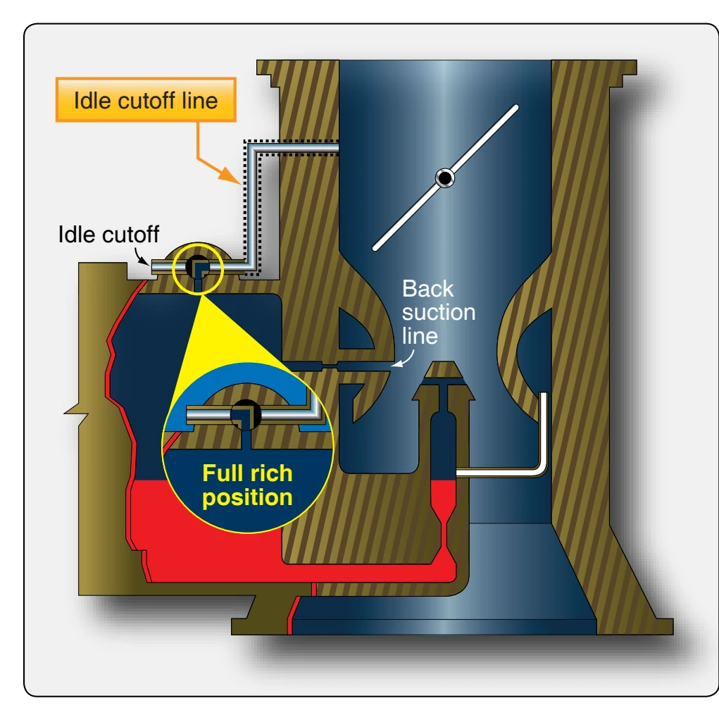
On float-type carburetors, two types of purely manual or flight deck controllable devices are in general use for controlling air-fuel mixtures, the needle type and the backsuction type. [Figures 2-16 and 2-17]
With the needle-type system, manual control is provided by a
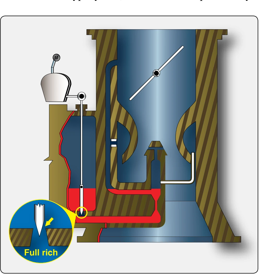
needle valve in the base of the float chamber. [Figure 2-16] This can be raised or lowered by adjusting a control in the flight deck. Moving the control to “rich,” opens the needle valve wide, which permits the fuel to flow unrestricted to the nozzle. Moving the control to “lean,” partially closes the valve and restricts the flow of fuel to the nozzle.
The back-suction-type mixture control system is the most widely used. [Figure 2-17] In this system, a certain amount of venturi low pressure acts upon the fuel in the float chamber so that it opposes the low pressure existing at the main discharge nozzle. An atmospheric line, incorporating an adjustable valve, opens into the float chamber. When the valve is completely closed, pressures on the fuel in the float chamber and at the discharge nozzle are almost equal, and fuel flow is reduced to maximum lean. With the valve wide open, pressure on the fuel in the float chamber is greatest and fuel mixture is richest. Adjusting the valve to positions between these two extremes controls the mixture. The quadrant in the flight deck is usually marked “lean” near the back end and “rich” at the forward end. The extreme back position is marked “idle cutoff” and is used when stopping the engine.
On float carburetors equipped with needle-type mixture control, placing the mixture control in idle cutoff seats the needle valve, thus shutting off fuel flow completely. On carburetors equipped with back-suction mixture controls, a separate idle cutoff line, leading to the extreme low pressure on the engine side of the throttle valve, is incorporated. (See the dotted line in Figure 2-17.) The mixture control is so linked that when it is placed in the “idle cutoff” position, it opens another passage that leads to piston suction. When placed in other positions, the valve opens a passage leading to the atmosphere. To stop the engine with such a system, close the throttle and place the mixture in the “idle cutoff” position. Leave the throttle in the closed position until the engine has stopped running and then open the throttle completely.
Accelerating System
When the throttle valve is opened quickly, a large volume of air rushes through the air passage of the carburetor; the amount of fuel that is mixed with the air is less than normal due to the slow response rate of the main metering system. As a result, after a quick opening of the throttle, the air-fuel mixture leans out momentarily. This can cause the engine to accelerate slowly or stumble as it tries to accelerate.