
Chapter 2
Engine Fuel & Fuel Metering Systems
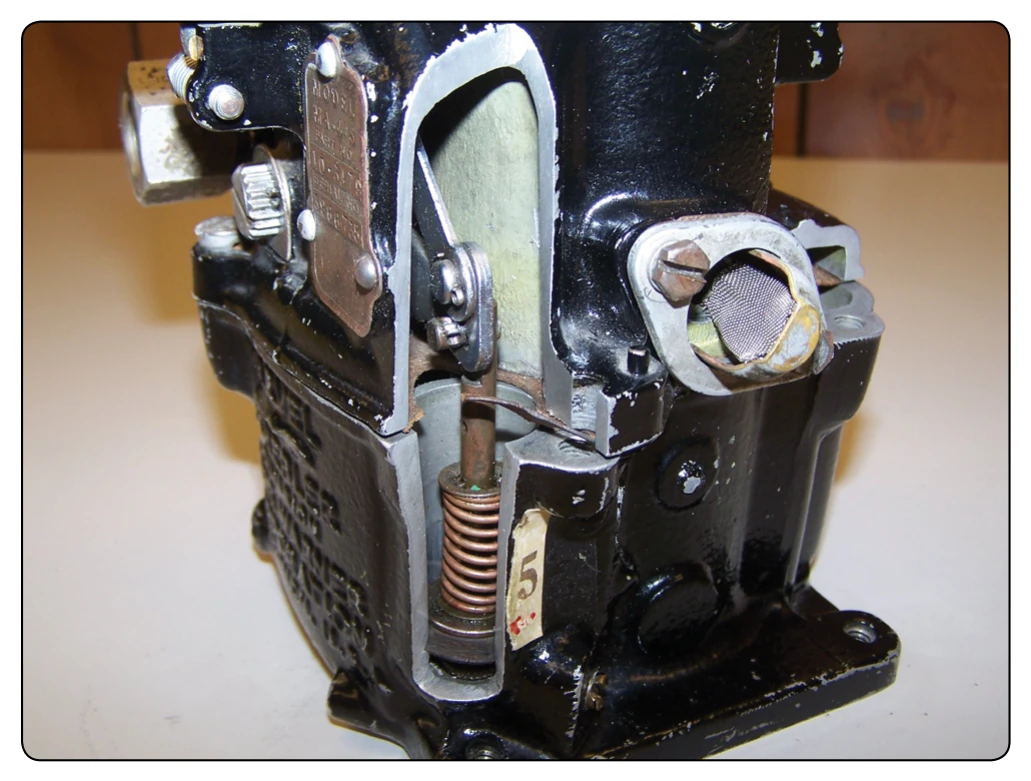
To overcome this tendency, the carburetor is equipped with a small fuel pump called an accelerating pump. A common type of accelerating system used in float carburetors is illustrated in Figure 2-18. It consists of a simple piston pump operated through linkage by the throttle control and a passageway opening into the main metering system or the carburetor barrel near the venturi. When the throttle is closed, the piston moves back, and fuel fills the cylinder. If the piston is pushed forward slowly, the fuel seeps past it back into the float chamber; if pushed rapidly, it sprays fuel in the venturi and enriches the mixture. An example of a cutaway accelerator pump is shown in Figure 2-19.
Economizer System
For an engine to develop maximum power at full throttle, the fuel mixture must be richer than for cruise. The additional fuel is used for cooling the engine combustion chambers to prevent detonation. An economizer is essentially a valve that is closed at throttle settings below approximately 60–70
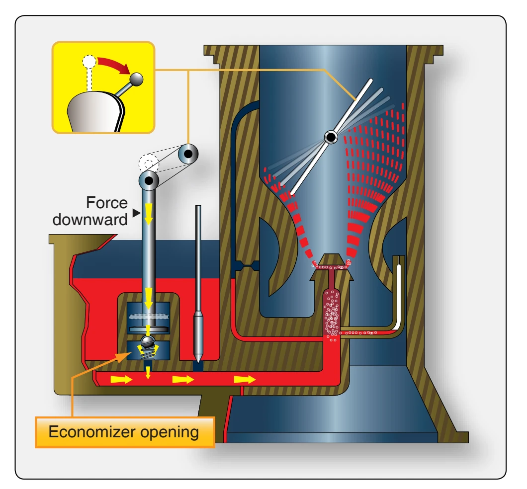
percent of rated power. This system, like the accelerating system, is operated by the throttle control.
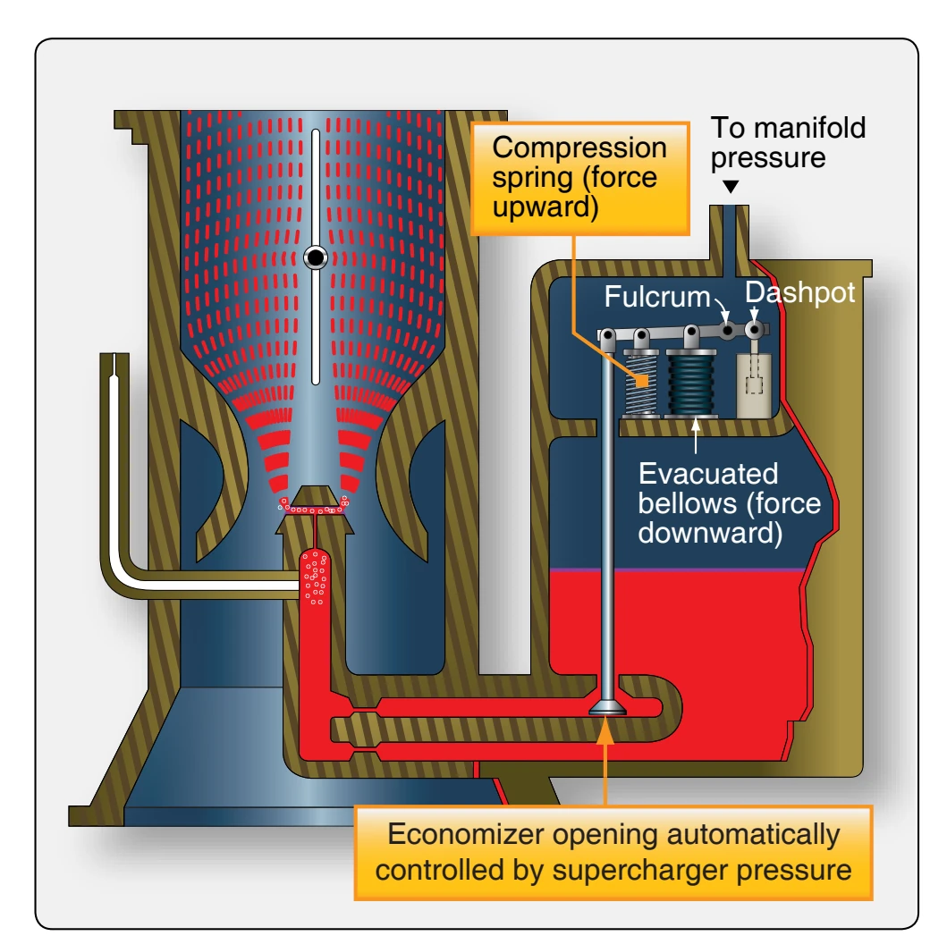
A typical economizer system consists of a needle valve which begins to open when the throttle valve reaches a predetermined point near the wide-open position. [Figure 2-20] As the throttle continues to open, the needle valve is opened further and additional fuel flows through it. This additional fuel supplements the flow from the main metering jet direct to the main discharge nozzle.
A pressure-operated economizer system is shown in Figure 2-21. This type has a sealed bellows located in an enclosed compartment. The compartment is vented to engine manifold pressure. When the manifold pressure reaches a
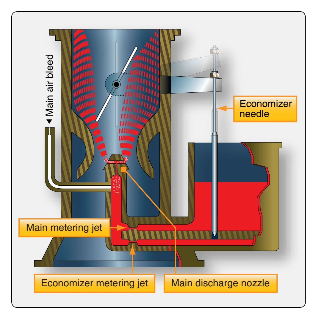
certain value, the bellows is compressed and opens a valve in a carburetor fuel passage, supplementing the normal quantity of fuel being discharged through the main nozzle.
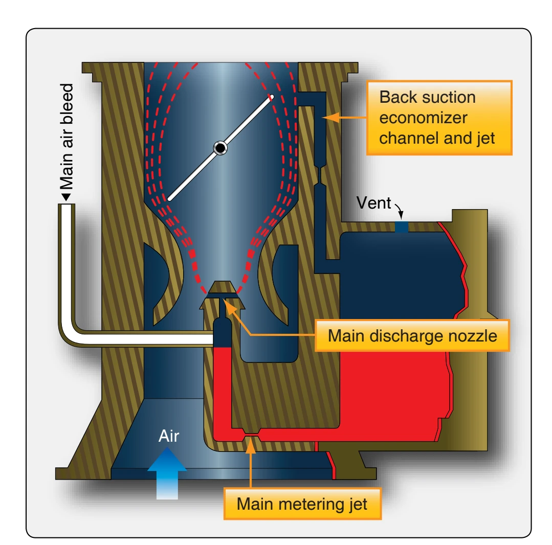
Another type of economizer is the back-suction system. [Figure 2-22] Fuel economy in cruising is provided by reducing the effective pressure acting on the fuel level in the float compartment. With the throttle valve in cruising position, suction is applied to the float chamber through an economizer hole and back-suction economizer channel and jet. The suction applied to the float chamber opposes the nozzle suction applied by the venturi. Fuel flow is reduced, leaning the mixture for cruising economy.
Another type of mixture control system uses a metering valve that is free to rotate in a stationary metering sleeve. Fuel enters the main and idling systems through a slot cut in the mixture sleeve. Fuel metering is accomplished by the relative position between one edge of the slot in the hollow metering valve and one edge of the slot in the metering sleeve. Moving the mixture control to reduce the size of the slot provides a leaner mixture for altitude compensation.
Pressure Injection Carburetors
Pressure injection carburetors are distinctly different from float-type carburetors as they do not incorporate a vented float chamber or suction pickup from a discharge nozzle located in the venturi tube. Instead, they provide a pressurized fuel system that is closed from the engine fuel pump to the discharge nozzle. The venturi serves only to create pressure differentials for controlling the quantity of fuel to the metering jet in proportion to airflow to the engine.
Typical Injection Carburetor
The injection carburetor is a hydromechanical device employing a closed feed system from the fuel pump to the discharge nozzle. It meters fuel through fixed jets according to the mass airflow through the throttle body and discharges it under a positive pressure.
The illustration in Figure 2-23 represents a pressure-type carburetor simplified so that only the basic parts are shown.