
Chapter 2
Engine Fuel & Fuel Metering Systems
When air passes through the carburetor to the engine, the pressure on the right of the diaphragm is lowered because of the drop in pressure at the venturi throat. As a result, the diaphragm moves to the right, opening the fuel valve. Pressure from the engine-driven pump then forces fuel through the open valve to the discharge nozzle, where it sprays into the airstream. The distance the fuel valve opens is determined by the difference between the two pressures acting on the diaphragm. This difference in pressure is proportional to the airflow through the carburetor. Thus, the volume of airflow determines the rate of fuel discharge.
The pressure injection carburetor is an assembly of the following units:
- Throttle body,
- Automatic mixture control,
- Regulator unit, and
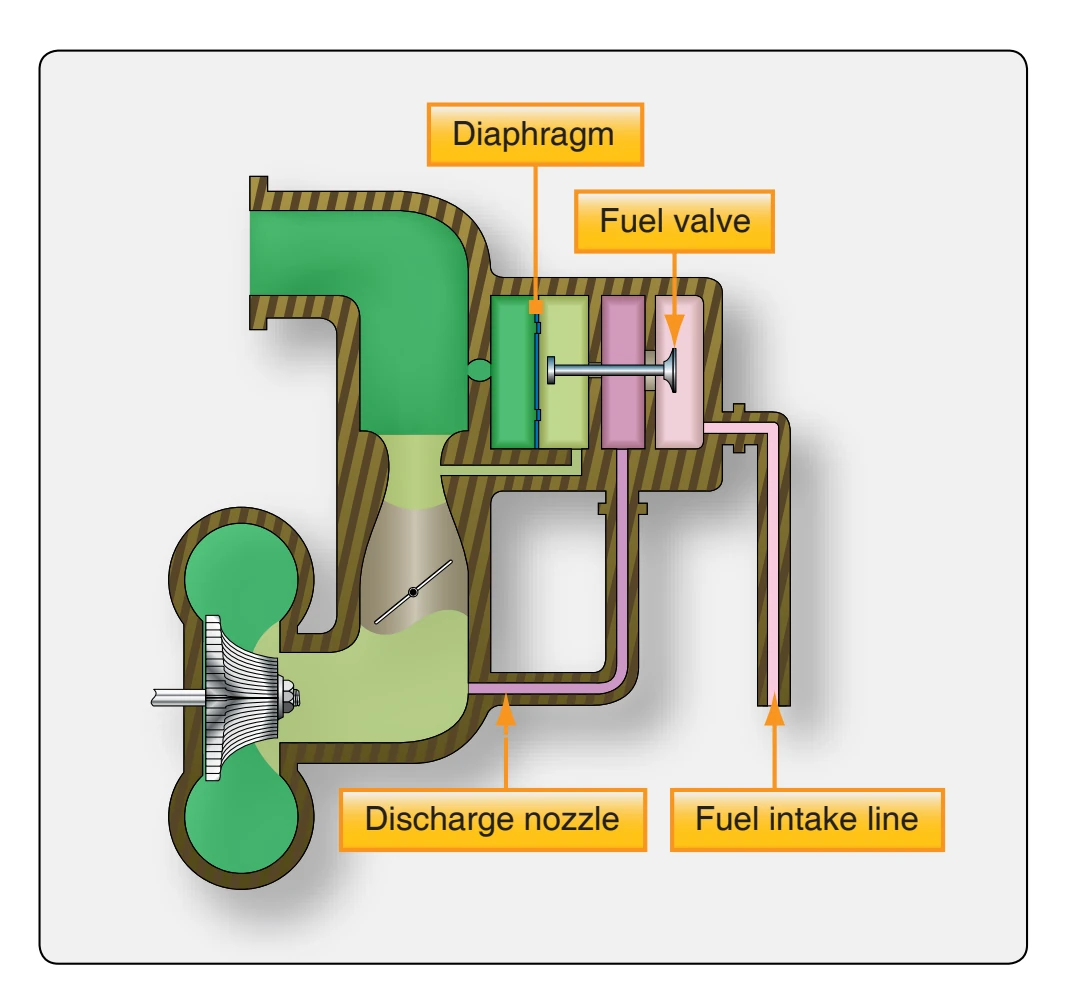
- Fuel control unit (some are equipped with an adapter).
Throttle Body
The throttle body contains the throttle valves, main venturi, boost venturi, and the impact tubes. All air entering the cylinders must flow through the throttle body; therefore, it is the air control and measuring device. The airflow is measured by volume and by weight so that the proper amount of fuel can be added to meet the engine demands under all conditions. As air flows through the venturi, its velocity is increased, and its pressure is decreased (Bernoulli’s principle). This low pressure is vented to the low pressure side of the air diaphragm [Figure 2-24 chamber B] in the regulator assembly. The impact tubes sense carburetor inlet air pressure and direct it to the automatic mixture control, which measures the air density. From the automatic mixture control, the air is directed to the high pressure side of the air diaphragm (chamber A). The pressure differential of the two chambers acting upon the air diaphragm is known as the air metering force which opens the fuel poppet valve.
The throttle body controls the airflow with the throttle valves. The throttle valves may be either rectangular or disc shaped, depending on the design of the carburetor. The valves are mounted on a shaft, which is connected by linkage to the idle valve and to the throttle control in the flight deck. A throttle stop limits the travel of the throttle valve and has an adjustment which sets engine idle speed.
Regulator Unit
The regulator is a diaphragm-controlled unit divided into five chambers and contains two regulating diaphragms and a poppet valve assembly. [Figure 2-24] Chamber A is
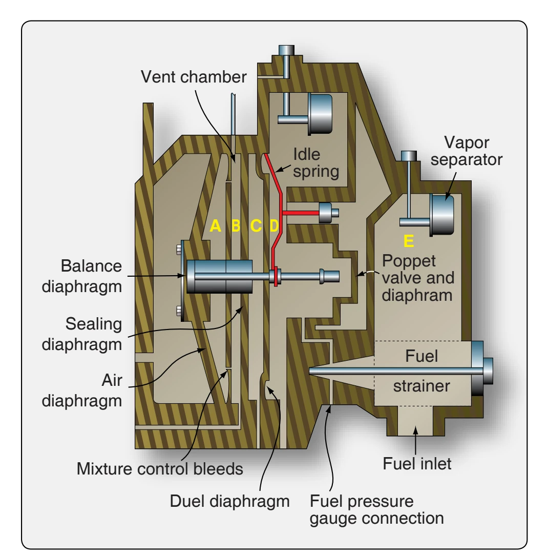
regulated air-inlet pressure from the air intake. Chamber B is boost venturi pressure. Chamber C contains metered fuel pressure controlled by the discharge nozzle or fuel feed valve. Chamber D contains unmetered fuel pressure controlled by the opening of the poppet valve. Chamber E is fuel pump pressure controlled by the fuel pump pressure relief valve. The poppet valve assembly is connected by a stem to the two main control diaphragms. The purpose of the regulator unit is to regulate the fuel pressure to the inlet side of the metering jets in the fuel control unit. This pressure is automatically regulated according to the mass airflow to the engine.
The carburetor fuel strainer (also called the gascolator), located in the inlet to chamber E, is a fine mesh screen through which all the fuel must pass as it enters chamber D. The strainer must be removed and cleaned at scheduled intervals.
Referring to Figure 2-24, assume that for a given airflow in lb/hr through the throttle body and venturi, a negative pressure of 1⁄ psi is established in chamber B. This tends 4 to move the diaphragm assembly and the poppet valve in a direction to open the poppet valve permitting more fuel to enter chamber D. The pressure in chamber C is held constant at 5 psi (10 psi on some installations) by the discharge nozzle or impeller fuel feed valve. Therefore, the diaphragm assembly and poppet valve moves in the open direction until the pressure in chamber D is 51⁄ psi. Under these pressures, 4 there is a balanced condition of the diaphragm assembly with a pressure drop of 1⁄ psi across the jets in the fuel control unit 4 (auto-rich or auto-lean).
If nozzle pressure (chamber C pressure) rises to 51⁄ psi, the 2 diaphragm assembly balance is upset, and the diaphragm assembly moves to open the poppet valve to establish the necessary 53⁄ psi pressure in chamber D. Thus, the 1⁄4 4 psi differential between chamber C and chamber D is reestablished, and the pressure drop across the metering jets remains the same.
If the fuel inlet pressure is increased or decreased, the fuel flow into chamber D tends to increase or decrease with the pressure change causing the chamber D pressure to do likewise. This upsets the balanced condition previously established, and the poppet valve and diaphragm assembly respond by moving to increase or decrease the flow to reestablish the pressure at the 1⁄ psi differential.
4
The fuel flow changes when the mixture control plates are moved from auto-lean to auto-rich, thereby selecting a different set of jets or cutting one or two in or out of the system. When the mixture position is altered, the diaphragm and poppet valve assembly repositions to maintain the established pressure differential of 1⁄ psi between chambers 4 C and D, maintaining the established differential across the jets. Under low power settings (low airflows), the difference in pressure created by the boost venturi is not sufficient to accomplish consistent regulation of the fuel. Therefore, an idle spring, shown in Figure 2-24, is incorporated in the regulator. As the poppet valve moves toward the closed position, it contacts the idle spring. The spring holds the poppet valve off its seat far enough to provide more fuel than is needed for idling. This potentially overrich mixture is regulated by the idle valve. At idling speed, the idle valve restricts the fuel flow to the proper amount. At higher speeds, it is withdrawn from the fuel passage and has no metering effect.
Vapor vent systems are provided in these carburetors to eliminate fuel vapor created by the fuel pump, heat in the engine compartment, and the pressure drop across the poppet valve. The vapor vent is located in the fuel inlet (chamber E) or, on some models of carburetors, in both chambers D and E.
The vapor vent system operates in the following way. When air enters the chamber in which the vapor vent is installed, the air rises to the top of the chamber, displacing the fuel and lowering its level. When the fuel level has reached a predetermined position, the float (which floats in the fuel) pulls the vapor vent valve off its seat, permitting the vapor in the chamber to escape through the vapor vent seat, its connecting line, and back to the fuel tank.