
Chapter 3
Induction & Exhaust Systems
The collector tubes terminate at the exhaust ejector openings at the firewall and are tapered to deliver the exhaust gases at the proper velocity to induce airflow through the exhaust
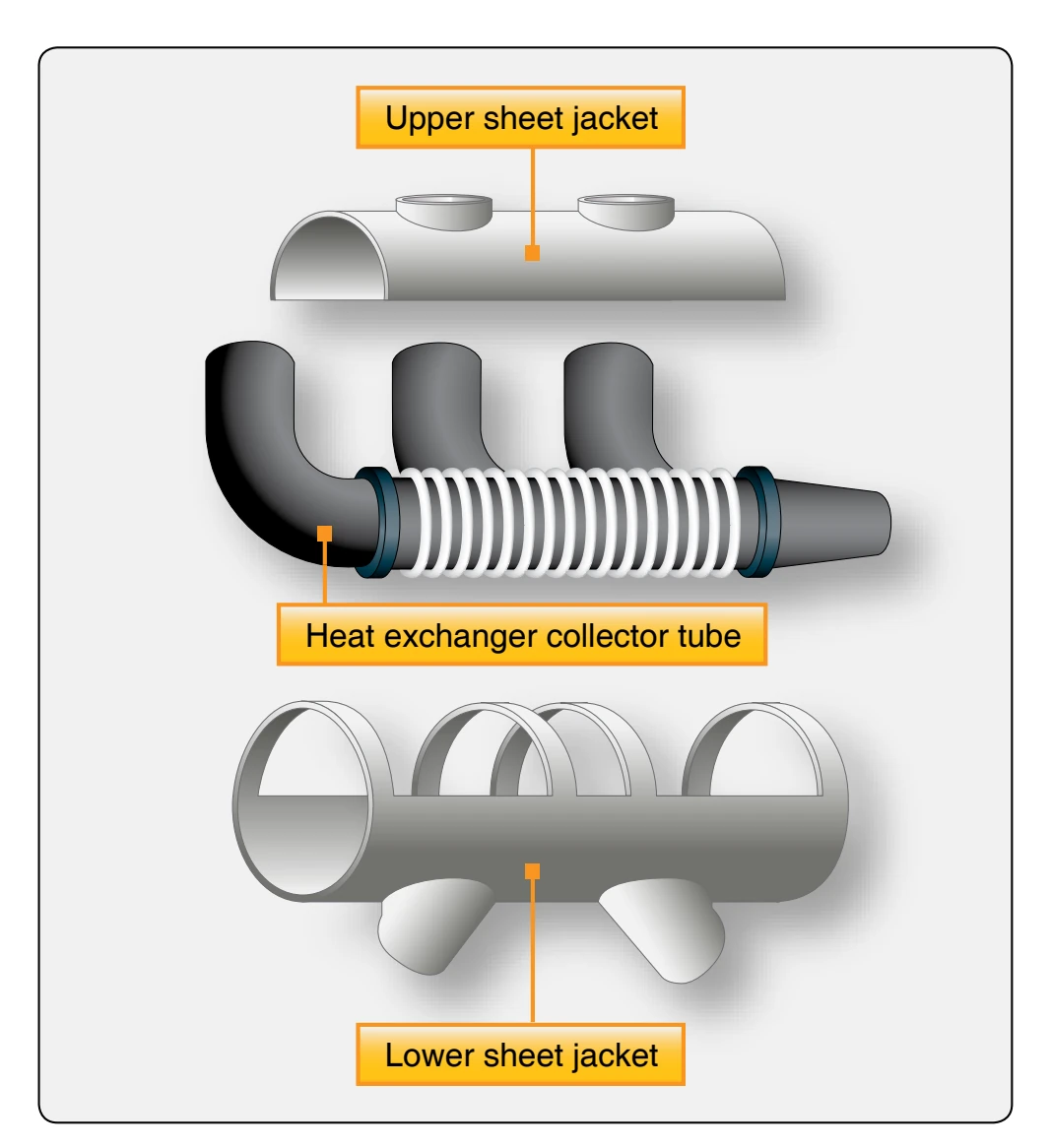
ejectors. The exhaust ejectors consist of a throat-and-duct assembly that utilizes the pumping action of the exhaust gases to induce a flow of cooling air through all parts of the engine compartment (augmenter tube action).
Radial Engine Exhaust Collector Ring System
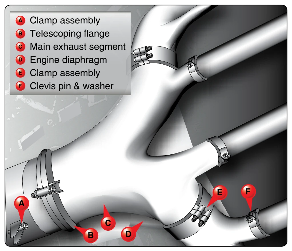
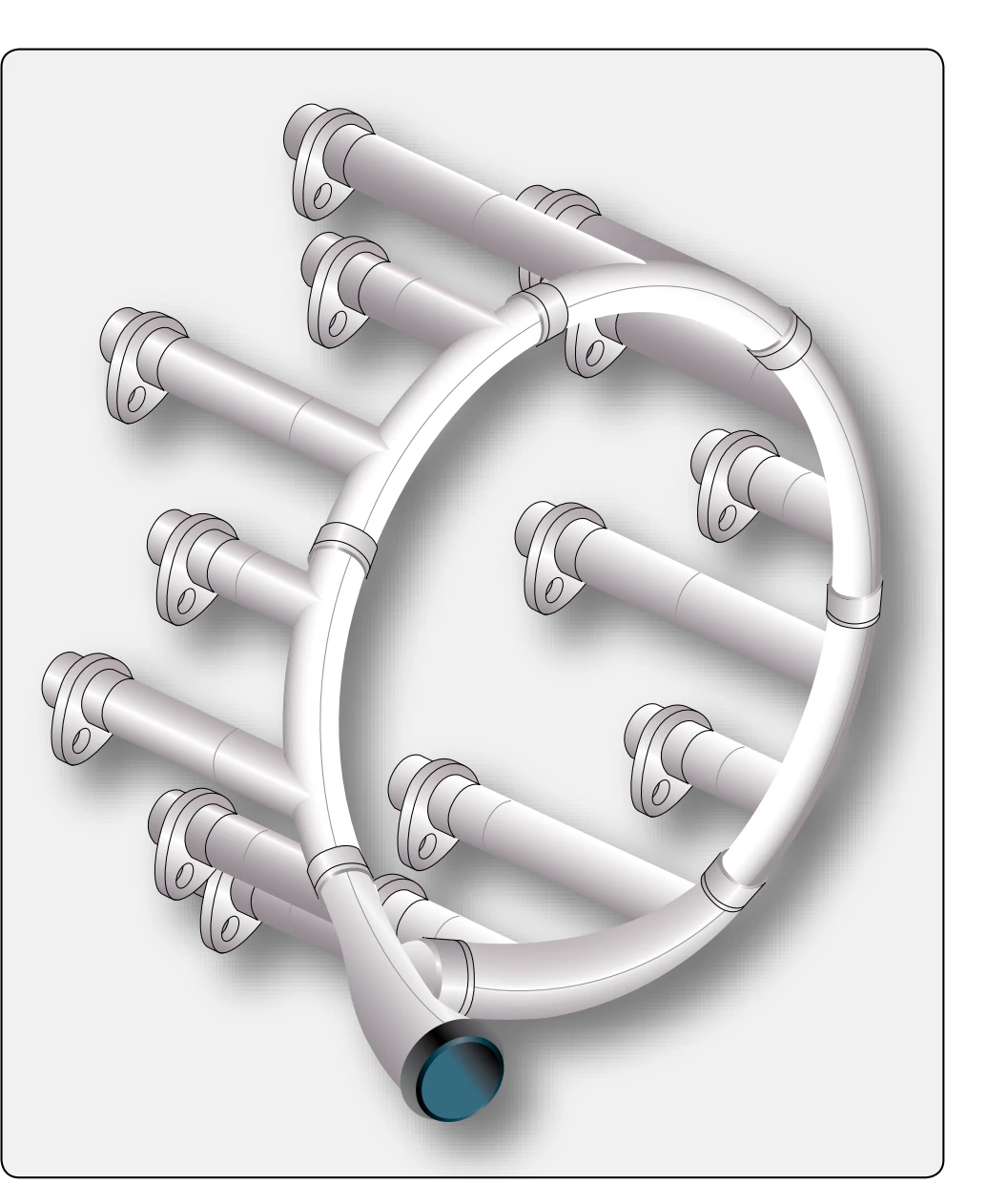
Figure 3-40 shows the exhaust collector ring installed on a 14-cylinder radial engine. The collector ring is a welded corrosion-resistant steel assembly manufactured in seven sections, with each section collecting the exhaust from two cylinders. The sections are graduated in size. [Figure 3-41] The small sections are on the inboard side, and the largest sections are on the outboard side at the point where the tailpipe connects to the collector ring. Each section of the collector ring is bolted to a bracket on the blower section of the engine and is partly supported by a sleeve connection between the collector ring ports and the short stack on the engine exhaust ports. The exhaust tailpipe is joined to the collector ring by a telescoping expansion joint, which allows enough slack for the removal of segments of the collector ring without removing the tailpipe. The exhaust tailpipe is a welded, corrosionresistant steel assembly consisting of the exhaust tailpipe and, on some aircraft, a muff-type heat exchanger.
Manifold & Augmentor Exhaust Assembly
Some radial engines are equipped with a combination exhaust manifold and augmentor assembly. On a typical 18-cylinder engine, two exhaust assemblies and two augmentor assemblies are used. Each manifold assembly collects exhaust gases from nine cylinders and discharges the gases into the forward end of the augmentor assembly. The exhaust gases are directed into the augmentor bellmouths. The augmentors are designed to produce a venturi effect to draw an increased airflow over the engine to augment engine
cooling. An augmentor vane is located in each tailpipe. When the vane is fully closed, the cross-sectional area of the tailpipe is reduced by approximately 45 percent. The augmentor vanes are operated by an electrical actuator, and indicators adjacent to the augmentor vane switches in the flight deck show vane positions. The vanes may be moved toward the “closed” position to decrease the velocity of flow through the augmentor to raise the engine temperature. This system is only used with older aircraft that generally use radial engines.
Reciprocating Engine Exhaust System Maintenance Practices
Any exhaust system failure should be regarded as a severe hazard. Depending on the location and type of failure, an exhaust system failure can result in carbon monoxide poisoning of crew and passengers, partial or complete loss of engine power, or an aircraft fire. Cracks in components, leaking gaskets, or complete failure can cause serious problems in flight. Often, these failures can be detected before complete failure. Black soot around an exhaust gasket shows the gasket has failed. The exhaust system should be inspected very thoroughly.
Exhaust System Inspection
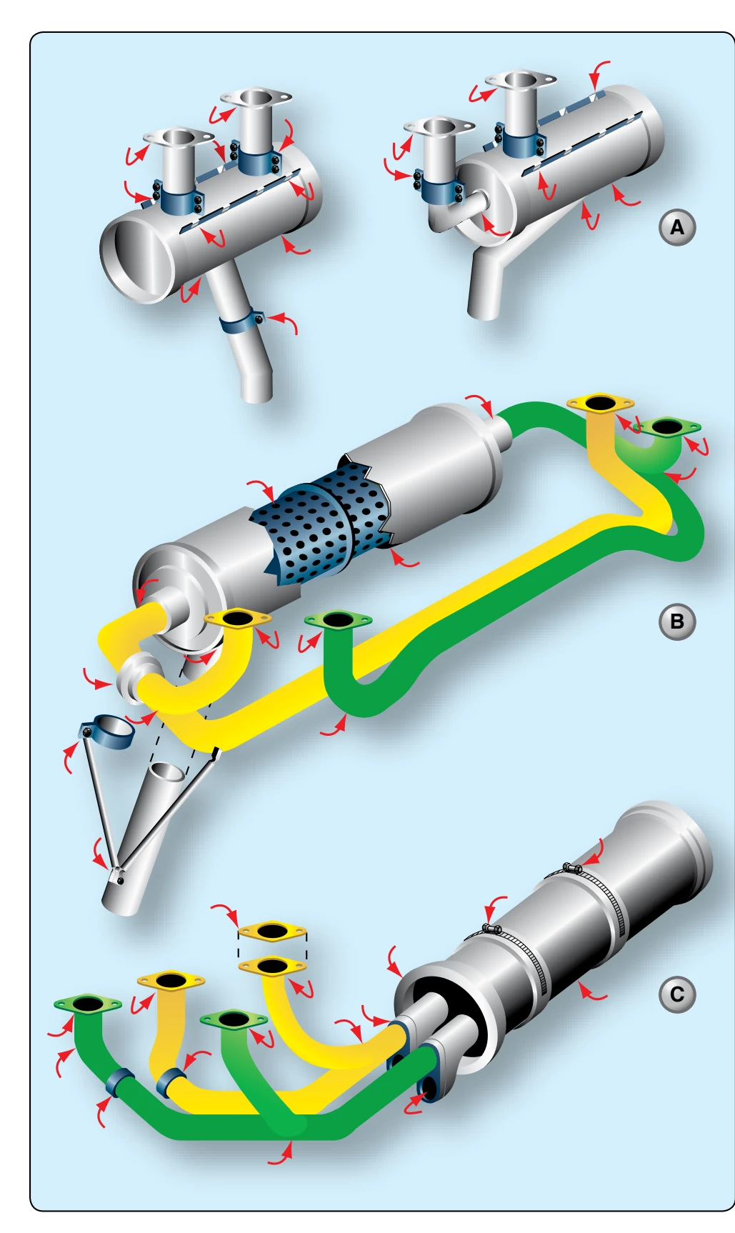
While the type and location of exhaust system components vary somewhat with the type of aircraft, the inspection requirements for most reciprocating engine exhaust systems are very similar. The following paragraphs include a discussion of the most common exhaust system inspection items and procedures for all reciprocating engines. Figure 3-42 shows the primary inspection areas of three types of exhaust systems.
When performing maintenance on exhaust systems, never use galvanized or zinc-plated tools on the exhaust system. Exhaust system parts should never be marked with a lead pencil. The lead, zinc, or galvanized mark is absorbed by the metal of the exhaust system when heated, creating a distinct change in its molecular structure. This change softens the metal in the area of the mark, causing cracks and eventual failure.
After the installation of a complete exhaust system and all pieces of engine cowl are installed and secured, the engine should be operated to allow the exhaust system to heat up to normal operating temperatures. The engine is then shut
down and the cowling removed to expose the exhaust system. Each clamped connection and each exhaust port connection should be inspected for evidence of exhaust gas leakage.
An exhaust leak is indicated by a flat gray or a sooty black streak on the pipes in the area of the leak. An exhaust leak is usually the result of poor alignment of two mated exhaust system members. When a leaking exhaust connection is discovered, the clamps should be loosened, and the leaking units repositioned to ensure a gas-tight fit.
After repositioning, the system nuts should be retightened enough to eliminate any looseness without exceeding the specified torque. If tightening to the specified torque does not eliminate looseness, the bolts and nuts should be replaced since they have probably stretched. After tightening to the specified torque, all nuts should be safetied. With the cowling removed, all necessary cleaning operations can be performed. Some exhaust units are manufactured with a plain sandblast finish. Others may have a ceramic-coated finish. Ceramiccoated stacks should be cleaned by degreasing only. They should never be cleaned with sandblast or alkali cleaners.