
Chapter 3
Induction & Exhaust Systems
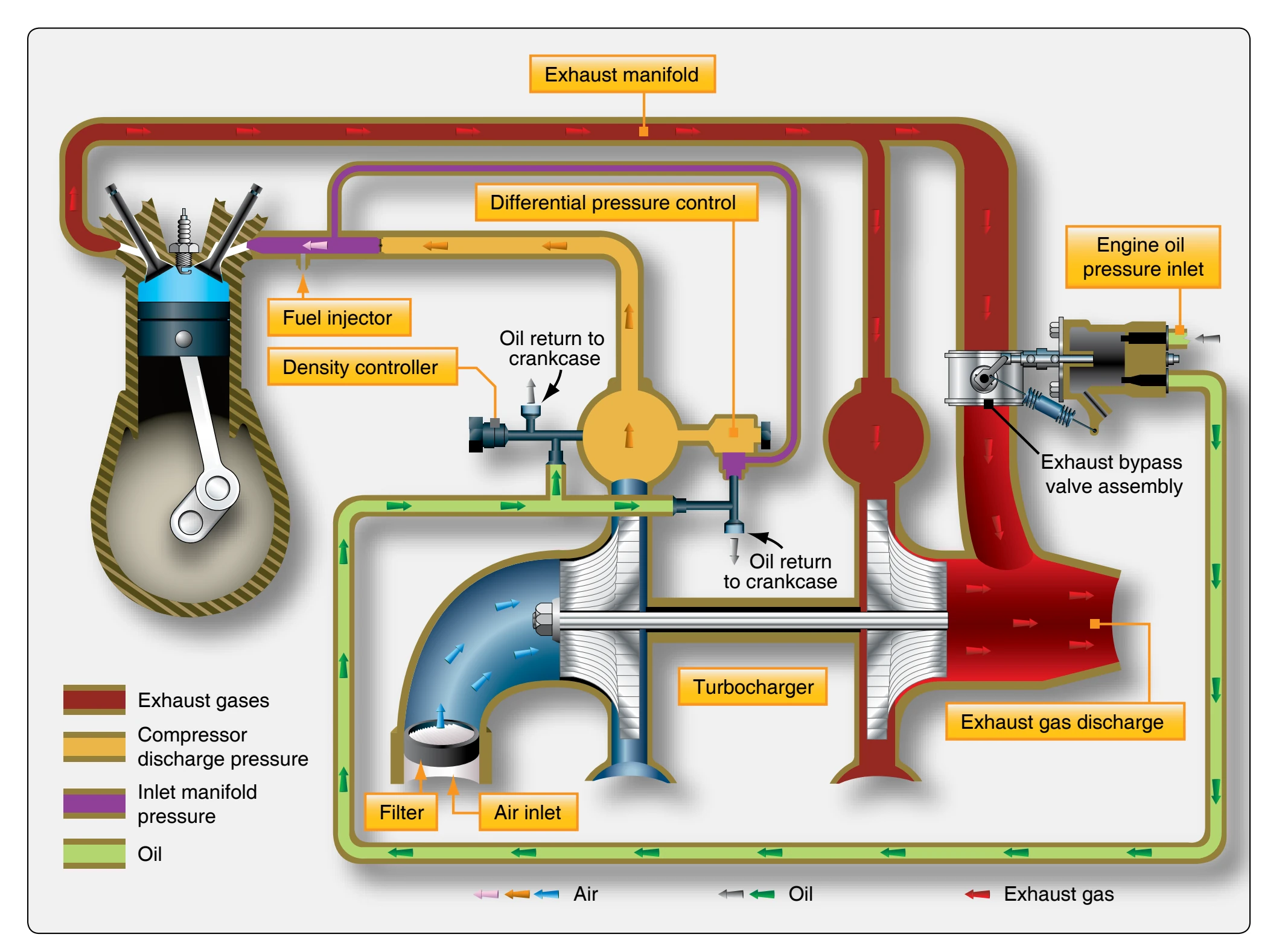
Figure 3-18 is a schematic of a sea level booster turbosupercharger system. This system used widely is automatically regulated by three components:
- Exhaust bypass valve assembly,
- Density controller, and
- Differential pressure controller.
By regulating the waste gate position and the “fully open” and “closed” positions, a constant power output can be maintained. When the waste gate is fully open, all the exhaust gases are directed overboard to the atmosphere, and no air is compressed and delivered to the engine air inlet. Conversely, when the waste gate is fully closed, a maximum volume of exhaust gases flows into the turbocharger turbine, and maximum supercharging is accomplished. Between these
two extremes of waste gate position, constant power output can be achieved below the maximum altitude at which the system is designed to operate. An engine with a critical altitude of 16,000 feet cannot produce 100 percent of its rated manifold pressure above 16,000 feet. Critical altitude means the maximum altitude at which, in standard atmosphere, it is possible to maintain, at a specified rotational speed, a specified power or a specified manifold pressure.
A critical altitude exists for every possible power setting below the maximum operating ceiling. If the aircraft is flown above this altitude without a corresponding change in the power setting, the waste gate is automatically driven to the fully closed position in an effort to maintain a constant power output. Thus, the waste gate is almost fully open at sea level and continues to move toward the closed position as the aircraft climbs, in order to maintain the preselected manifold pressure setting. When the waste gate is fully closed (leaving only a small clearance to prevent sticking), the manifold pressure begins to drop if the aircraft continues to climb. If a higher power setting cannot be selected, the turbocharger’s critical altitude has been reached. Beyond this altitude, the power output continues to decrease. If a turbocharger waste gate will not close fully, then the aircraft will not be able to reach its critical altitude.
The position of the waste gate valve, which determines power output, is controlled by oil pressure. Engine oil pressure acts on a piston in the waste gate assembly, which is connected by linkage to the waste gate valve. When oil pressure is increased on the piston, the waste gate valve moves toward the closed position, and engine output power increases. Conversely, when the oil pressure is decreased, the waste gate valve moves toward the open position, and output power is decreased as described earlier.
The position of the piston attached to the waste gate valve is dependent on bleed oil, which controls the engine oil pressure applied to the top of the piston. Oil is returned to the engine crankcase through two control devices, the density controller and the differential pressure controller. These two controllers, acting independently, determine how much oil is bled back to the crankcase and establishes the oil pressure on the piston.
The density controller is designed to limit the manifold pressure below the turbocharger’s critical altitude and regulates bleed oil only at the full throttle position. The pressure- and temperature-sensing bellows of the density controller react to pressure and temperature changes between the fuel injector inlet and the turbocharger compressor. The bellows, filled with dry nitrogen, maintain a constant density by allowing the pressure to increase as the temperature increases. Movement of the bellows repositions the bleed valve, causing a change in the quantity of bleed oil, which changes the oil pressure on top of the waste gate piston. [Figure 3-18]
The differential pressure controller functions during all positions of the waste gate valve other than the fully open position, which is controlled by the density controller. One side of the diaphragm in the differential pressure controller senses air pressure upstream from the throttle; the other side samples pressure on the cylinder side of the throttle valve. [Figure 3-18] At the “wide open” throttle position when the density controller controls the waste gate, the pressure across the differential pressure controller diaphragm is at a minimum and the controller spring holds the bleed valve closed. At “part throttle” position, the air differential is increased, opening the bleed valve to bleed oil to the engine crankcase and reposition the waste gate piston. Thus, the two controllers operate independently to control turbocharger operation at all positions of the throttle. Without the overriding function of the differential pressure controller during part-throttle operation, the density controller would position the waste gate valve for maximum power. The differential pressure controller reduces injector entrance pressure and continually repositions the valve over the whole operating range of the engine.
The differential pressure controller reduces the unstable condition known as “bootstrapping” during part-throttle operation. Bootstrapping is an indication of unregulated power change that results in the continual drift of manifold pressure. This condition can be illustrated by considering the operation of a system when the waste gate is fully closed. During this time, the differential pressure controller is not modulating the waste gate valve position. Any slight change in power caused by a change in temperature or rpm fluctuation is magnified and results in manifold pressure change since the slight change causes a change in the amount of exhaust gas flowing to the turbine. Any change in exhaust gas flow to the turbine causes a change in power output and is reflected in manifold pressure indications. Bootstrapping, then, is an undesirable cycle of turbocharging events causing the manifold pressure to drift in an attempt to reach a state of equilibrium.
Bootstrapping is sometimes confused with the condition known as overboost, but bootstrapping is not a condition that is detrimental to engine life. An overboost condition is one in which manifold pressure exceeds the limits prescribed for a particular engine and can cause serious damage. A pressure relief valve when used in some systems, set slightly in excess of maximum deck pressure, is provided to prevent damaging over boost in the event of a system malfunction.
The differential pressure controller is essential to smooth functioning of the automatically controlled turbocharger, since it reduces bootstrapping by reducing the time required to bring a system into equilibrium. There is still extra throttle sensitivity with a turbocharged engine than with a naturally aspirated engine. Rapid movement of the throttle can cause a certain amount of manifold pressure drift in a turbocharged engine. Less severe than bootstrapping, this condition is called overshoot. While overshoot is not a dangerous condition, it can be a source of concern to the pilot or operator who selects a particular manifold pressure setting only to find it has changed in a few seconds and must be reset. Since the automatic controls cannot respond rapidly enough to abrupt changes in throttle settings to eliminate the inertia of turbocharger speed changes, overshoot must be controlled by the operator. This can best be accomplished by slowly making changes in throttle setting, accompanied by a few seconds’ wait for the system to reach a new equilibrium. Such a procedure is effective with turbocharged engines, regardless of the degree of throttle sensitivity.
Turbocharger Controllers & System Descriptions
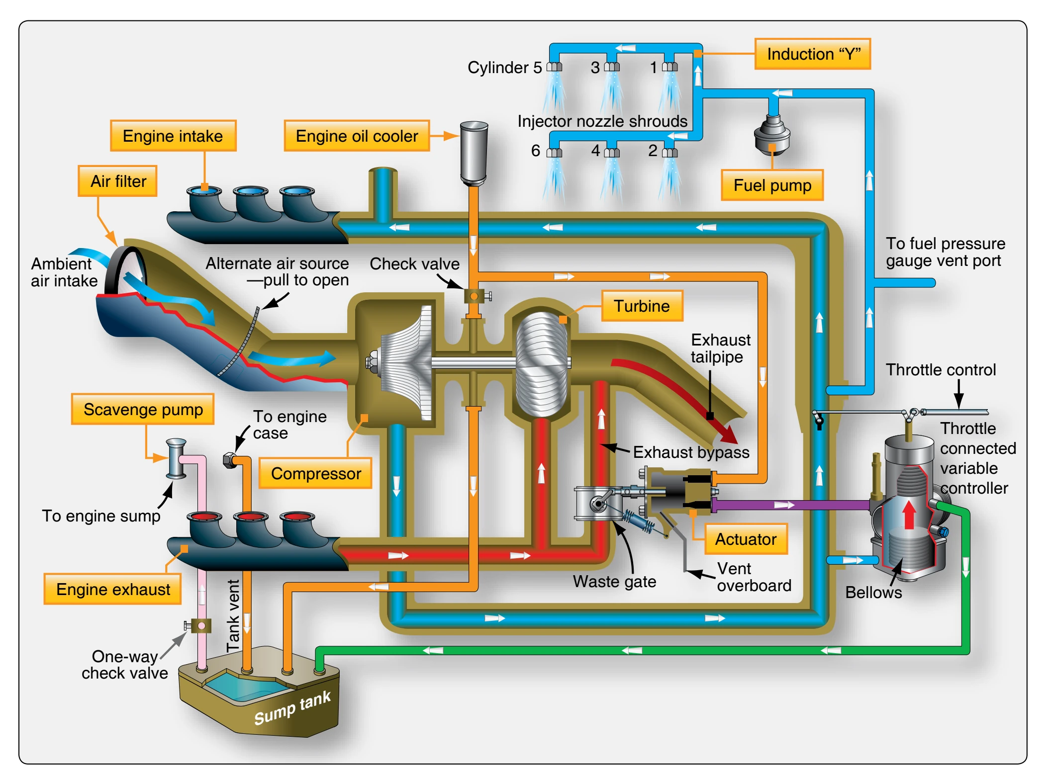
Turbocharger system engines contain many of the same components mentioned with the previous systems. [Figure 3-19] Some systems use special lines and fittings that are connected to the upper-deck pressure for air reference to the fuel injection system and in some cases for pressurizing the magnetos. Basic system operation is similar to other turbocharger systems with the main differences being in the controllers. The controller monitors deck pressure by sensing the output of the compressor. The controller controls the oil flow through the waste gate actuator, which opens or closes the exhaust bypass valve. If a malfunction occurs causing the waste gate or controller to not be stable, it will cause the engine to surge due to an erratic manifold pressure. When deck pressure is insufficient, the controller restricts oil flow thereby increasing oil pressure at the waste gate actuator. This pressure acts on the piston to close off the waste gate valve,
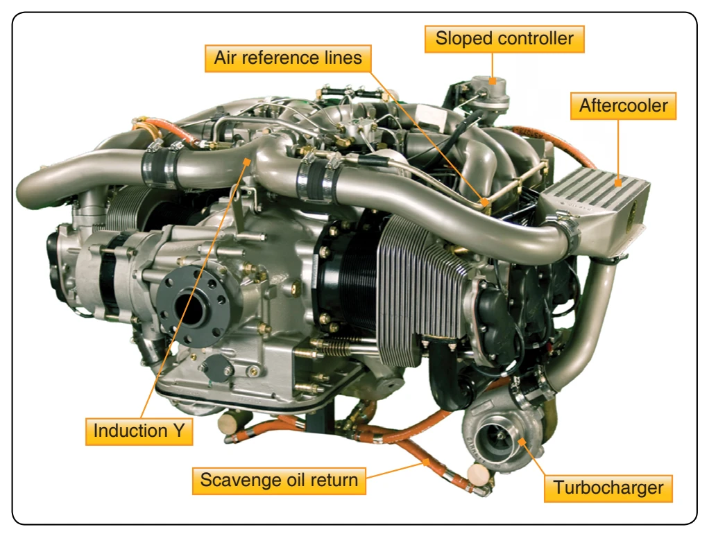
forcing more exhaust gas pulses to turn the turbine faster and cause an increase in compressor output. When deck pressure is too great, the opposite occurs. The exhaust waste gate fully opens and bypasses some of the exhaust gases to decrease exhaust flow across the turbine. An aftercooler is installed in the induction air path between the compressor stage and the air throttle inlet. [Figure 3-20]
Most turbochargers are capable of compressing the induction air to the point at which it can raise the air temperature by a factor of five. This means that full power takeoff on a 100 °F day could produce induction air temperatures exiting the compressor at up to 500 °F. This would exceed the allowable throttle air inlet temperature on all reciprocating engine models. Typically, the maximum air throttle inlet temperature ranges from a low 230 °F to a high of 300 °F. Exceeding these maximums can place the combustion chambers closer to detonation. The function of the aftercooler is to cool the compressed air, which decreases the likelihood of detonation and increases the charge air density, which improves the turbocharger performance for that engine design. On engine start, the controller senses insufficient compressor discharge pressure (deck pressure) and restricts the flow of oil from the waste gate actuator to the engine. This causes the waste gate butterfly valve to close. As the throttle is advanced, exhaust gas flows across the turbine increases, thereby increasing turbine/compressor shaft speed and compressor discharge pressure. The controller senses the difference between upper deck and manifold pressure. If either deck pressure or throttle differential pressure rises, the controller poppet valve opens, relieving oil pressure to the waste gate actuator. This decreases turbocharger compressor discharge pressure (deck pressure).