
Chapter 3
Induction & Exhaust Systems
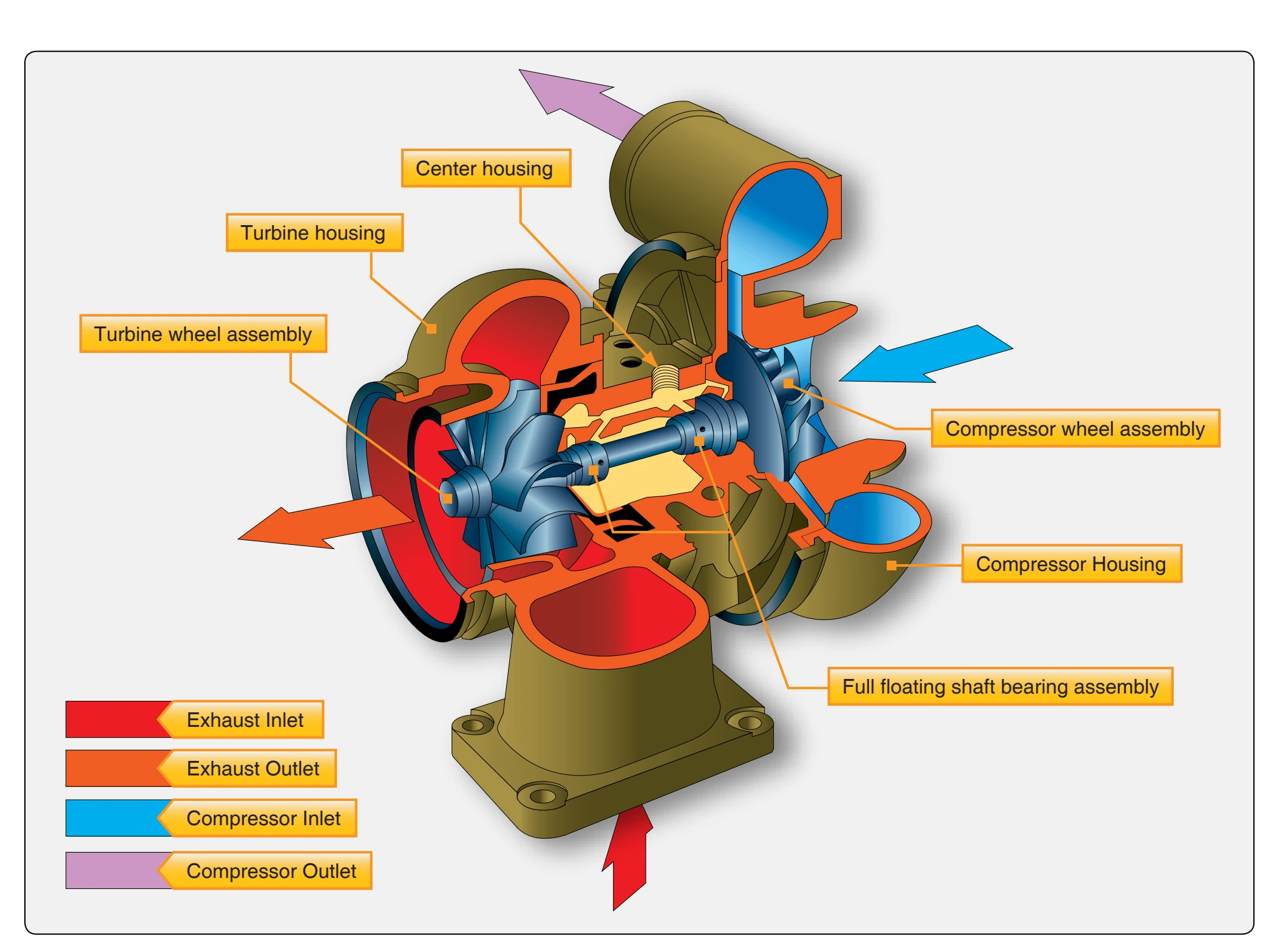
The typical turbosupercharger, shown in Figure 3-12, is composed of three main parts:
- Compressor assembly,
- Turbine wheel assembly, and
- A full floating shaft bearing assembly.
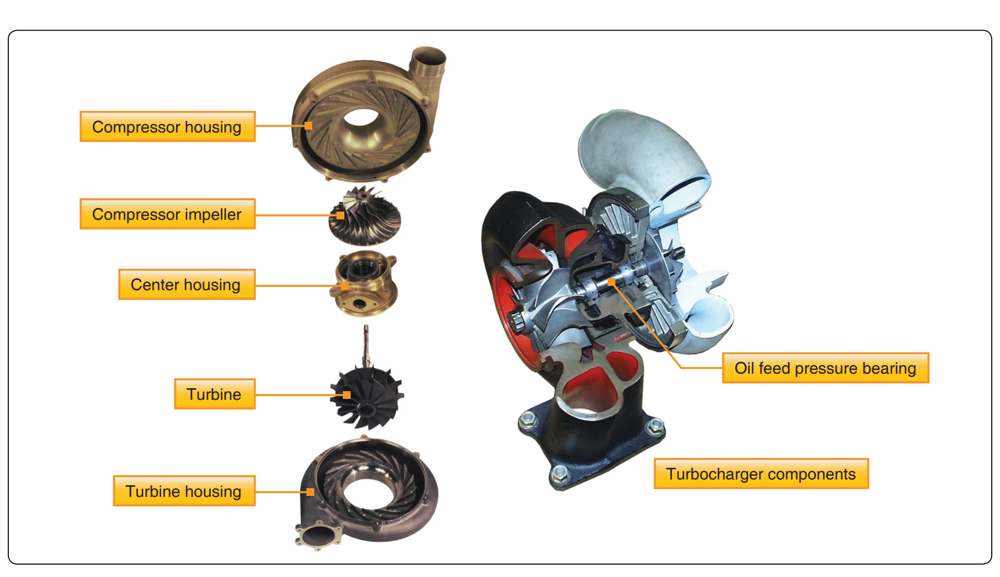
Detail examples of a turbosupercharger are shown in Figure 3-13. In addition to the major assemblies, there is a baffle between the compressor casing and the exhaust-gas turbine that directs cooling air to the pump and bearing casing, and also shields the compressor from the heat radiated by the turbine. In installations where cooling air is limited, the baffle is replaced by a regular cooling shroud that receives its air directly from the induction system.
The compressor assembly is made up of an impeller, a diffuser, and a casing. The air for the induction system enters through a circular opening in the center of the compressor casing, where it is picked up by the blades of the impeller, which gives it high velocity as it travels outward toward the diffuser. The diffuser vanes direct the airflow as it leaves the impeller and also converts the high velocity of the air to high-pressure.
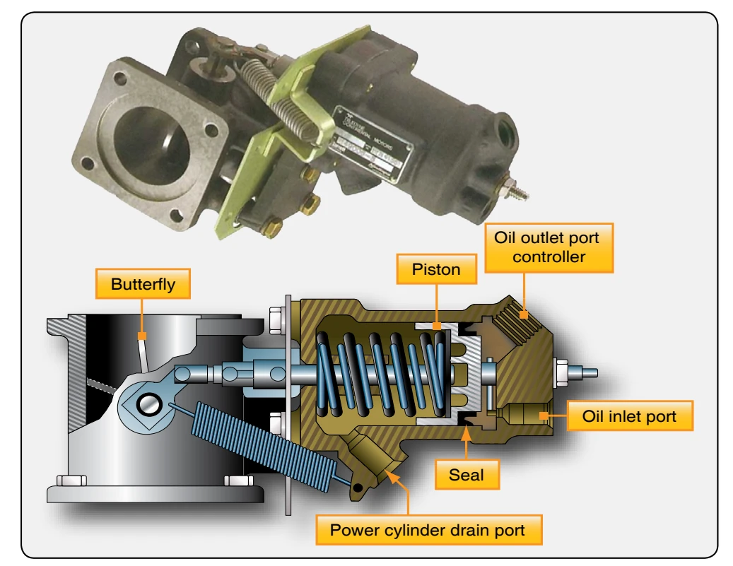
Motive power for the impeller is furnished through the impeller’s attachment to the turbine wheel shaft of the exhaust-gas turbine. This complete assembly is referred to as the rotor. (The rotor revolves on the oil feed bearings.) The exhaust gas turbine assembly consists of the turbocharger and waste gate valve. [Figure 3-14] The turbine wheel, driven by exhaust gases, drives the impeller. The turbo housing collects and directs the exhaust gases onto the turbine wheel, and the waste gate regulates the amount of exhaust gases directed to the turbine. The waste gate controls the volume of the exhaust gas that is directed onto the turbine and thereby regulates the speed of the rotor (turbine and impeller). [Figure 3-15]
If the waste gate is completely closed, all the exhaust gases are “backed up” and forced through the turbine wheel. If the waste gate is partially closed, a corresponding amount of exhaust gas is directed to the turbine. The exhaust gasses, thus directed, strike the turbine blades, arranged radially around the outer edge of the turbine, and cause the rotor (turbine and impeller) to rotate. The gases, having exhausted most of their energy, are then exhausted overboard. When the waste gate is fully open, nearly all of the exhaust gases pass overboard providing little or no boost.
Normalizer Turbocharger
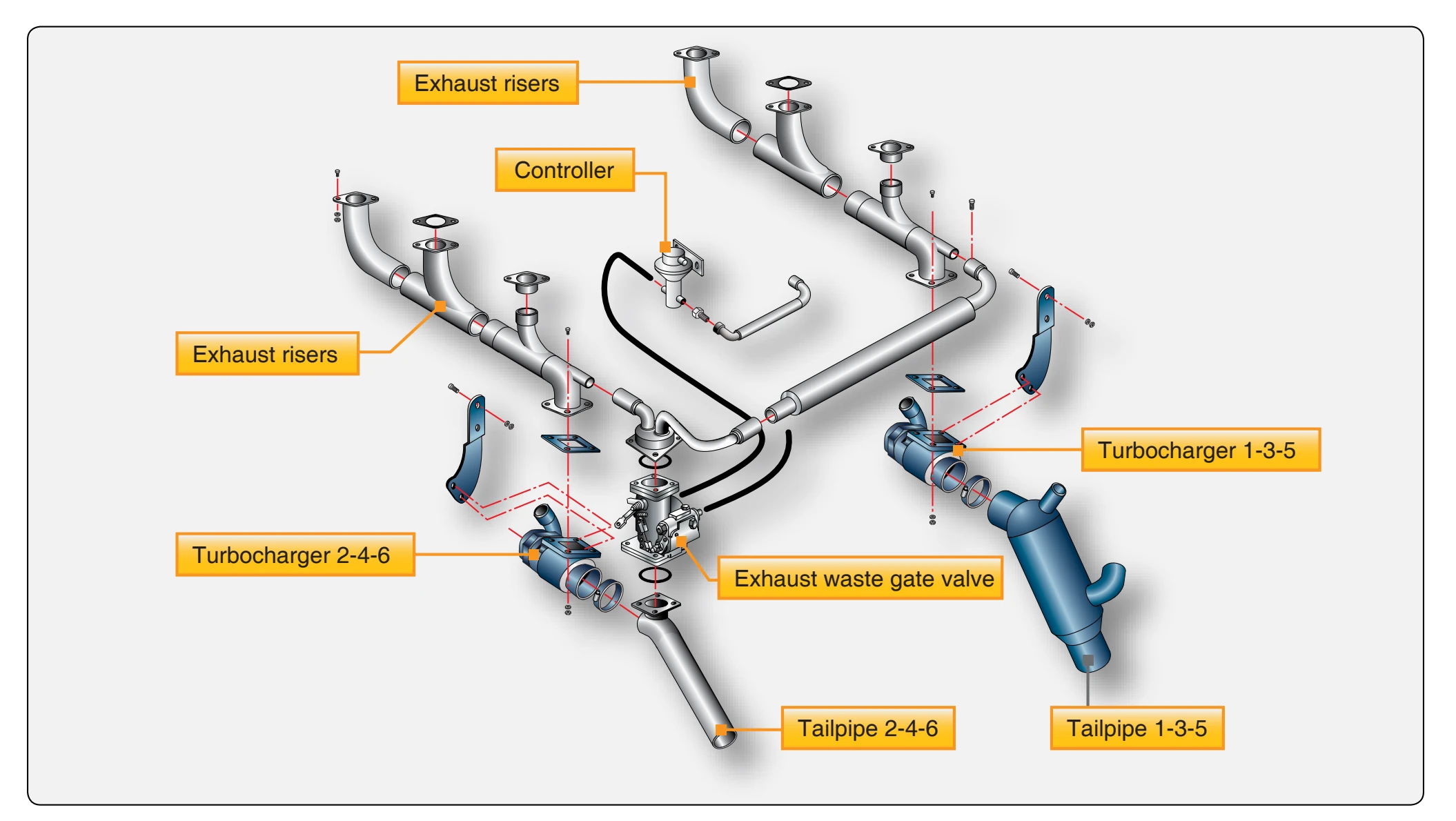
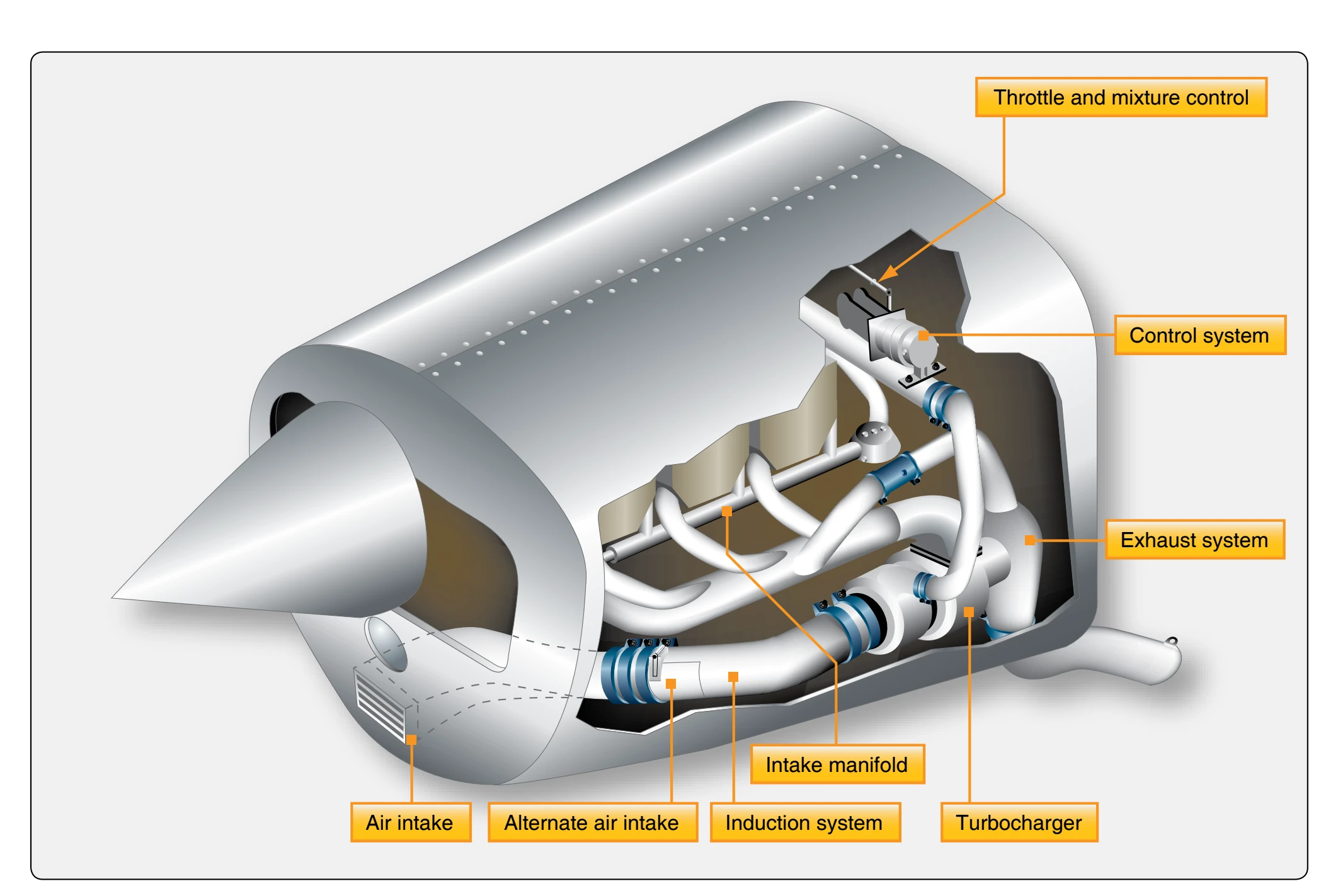
Some engines used in light aircraft are equipped with an externally driven normalizing system. These systems are powered by the energy of exhaust gases and are usually referred to as “normalizing turbocharger” systems. These systems were not designed to be used as a true supercharger (boost manifold pressure over 30 "Hg). They compensate for the power lost due to the pressure drop resulting from increased altitude. On many small aircraft engines, the turbocharger (normalizing) system is designed to be operated only above a certain altitude, 5,000 feet for example, since maximum power without normalizing is available below that altitude. The location of the air induction and exhaust systems of a typical normalizing turbocharger system for a small aircraft is shown in Figure 3-16.
Ground-Boosted Turbosupercharger System
Some ground-boosted (sea level) turbosupercharged systems are designed to operate from sea level up to their critical altitude. These engines, sometimes referred to as sea level-boosted engines, can develop more power at sea level than an engine without turbosupercharging. As was mentioned earlier, an engine must be boosted above 30 "Hg to truly be supercharged. This type of turbocharger accomplishes this by increasing the manifold pressure above 30 "Hg to around 40 "Hg.
The turbosupercharger air induction system consists of a filtered ram-air intake located on the side of the nacelle. [Figure 3-17] An alternate air door within the nacelle permits compressor suction automatically to admit alternate air (heated engine compartment air) if the induction air filter becomes clogged. In many cases, the alternate air door can be operated manually in the event of filter clogging.
Almost all turbocharger systems use engine oil as the control fluid for controlling the amount of boost (extra manifold pressure) provided to the engine. The waste-gate actuator and controllers use pressurized engine oil for their power supply. The turbocharger is controlled by the waste gate and waste gate actuator. The waste gate actuator, which is physically connected to the waste gate by mechanical linkage, controls
the position of the waste gate butterfly valve. The waste gate bypasses the engine exhaust gases around the turbocharger turbine inlet. By controlling the amount of exhaust gases that pass through the turbine of the turbocharger, the speed of the compressor and the amount of intake boost (upper deck pressure) is controlled. Engine oil is also used to cool and lubricate the bearings that support the compressor and turbine in the turbocharger. Turbocharger lubricating oil is engine oil supplied through the engine oil system. An oil supply hose from the rear of the oil cooler directs oil to the turbocharger center housings and bearings. Oil hoses return oil from the turbochargers to the oil scavenge pump located on the rear of the engine. The one-way check valve in the oil supply line prevents oil from draining into the turbocharger while the engine is not operating. Piston ring-like oil seals are used on the compressor wheel shaft to prevent the lubricating oil from entering the turbine and compressor housings from the center housing.
The position of the waste gate is controlled by adjusting the oil pressure in the waste gate actuator. Several different types of controllers are used to provide the correct pressure in the waste gate actuator. This is done either by restricting the oil flow or by allowing the oil to return to the engine. The more the oil is restricted, the more pressure is in the waste gate actuator and the more closed the waste gate is. This causes the exhaust gases to pass through the turbine, increasing the speed of the compressor raising the inlet pressure. The reverse happens if the oil is not restricted by the controllers and boost is reduced. The pressure from the outlet of the compressor of the turbocharger to the throttle is referred to as deck pressure or upper deck pressure.