
Chapter 4
Engine Ignition & Electrical Systems
Engine Ignition &
Reciprocating Engine Ignition Systems
The basic requirements for reciprocating engine ignition systems are similar, regardless of the type of engine. All ignition systems must deliver a high-tension spark across the electrodes of each spark plug in each cylinder of the engine in the correct firing order. At a predetermined number of degrees ahead of the top dead center position of the piston, as measured by crankshaft travel in degrees of rotation, the spark occurs in the cylinder. The potential output voltage of the system must be adequate to arc the gap in the spark plug electrodes under all operating conditions. The spark plug is threaded into the cylinder head with the electrodes exposed to the combustion area of the engine’s cylinder.
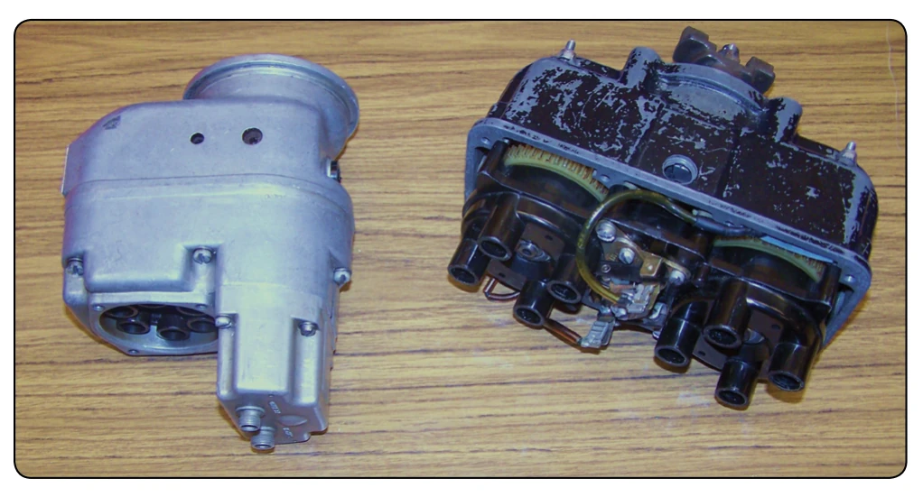
Ignition systems can be divided into two classifications: magneto-ignition systems or electronic Full Authority Digital Engine Control (FADEC) systems for reciprocating engines. Ignition systems can also be subclassified as either single or dual magneto-ignition systems. The single magneto-ignition system, usually consisting of one magneto and the necessary wiring, was used with another single magneto on the same engine. Dual magnetos generally use one rotating magnet that feeds two complete magnetos in one magneto housing. An example of each type is shown in Figure 4-1.
Aircraft magneto-ignition systems can be classified as either high-tension or low-tension. The low-tension magneto system, covered in a later section of this chapter, generates a low-voltage that is distributed to a transformer coil near each spark plug. This system eliminates some problems inherent in the high-tension system that was containing the high-voltage until it passed through the spark plug. The materials that were used for ignition leads could not withstand the high-voltage
Electrical Systems
and were prone to leak to ground before the spark would get to the cylinder. As new materials evolved and shielding was developed, the problems with high-tension magnetos were overcome. The high-tension magneto system is still the most widely used aircraft ignition system.
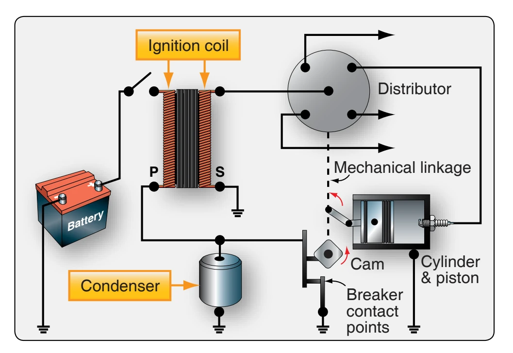
Some very old antique aircraft used a battery-ignition system. In this system, the source of energy is a battery or generator, rather than a magneto. This system was similar to that used in most automobiles at the time. Figure 4-2 shows a simplified schematic of a battery-ignition system.
Magneto-Ignition System Operating Principles
The magneto, a special type of engine-driven alternating current (AC) generator, uses a permanent magnet as a source of energy. By the use of a permanent magnet (basic magnetic field), coil of wire (concentrated lengths of conductor), and relative movement of the magnetic field, current is generated in the wire. At first, the magneto generates electrical power by the engine rotating the permanent magnet and inducing a current to flow in the coil windings. As current flows through the coil windings, it generates its own magnetic field that surrounds the coil windings. At the correct time, this current flow is stopped and the magnetic field collapses across a second set of windings in the coil and a high-voltage is generated. This is the voltage used to arc across the spark plug gap. In both cases, the three basic things needed to generate electrical power are present to develop the highvoltage that forces a spark to jump across the spark plug gap
in each cylinder. Magneto operation is timed to the engine so that a spark occurs only when the piston is on the proper stroke at a specified number of crankshaft degrees before the top dead center piston position.
High-Tension Magneto System Theory of Operation
The high-tension magneto system can be divided, for purposes of discussion, into three distinct circuits: magnetic, primary electrical, and secondary electrical circuits.
Magnetic Circuit
The magnetic circuit consists of a permanent multi-pole rotating magnet, a soft iron core, and pole shoes. [Figure 4-3] The magnet is geared to the aircraft engine and rotates in the gap between two pole shoes to furnish the magnetic lines of force (flux) necessary to produce an electrical voltage. The poles of the magnet are arranged in alternate polarity so that the flux can pass out of the north pole through the coil core and back to the south pole of the magnet. When the magnet is in the position shown in Figure 4-3A, the number of magnetic lines of force through the coil core is maximum because two magnetically opposite poles are perfectly aligned with the pole shoes.
This position of the rotating magnet is called the full register position and produces a maximum number of magnetic lines of force, flux flow clockwise through the magnetic circuit and from left to right through the coil core. When the magnet is moved away from the full register position, the amount of flux passing through the coil core begins to decrease. This occurs because the magnet’s poles are moving away from the pole shoes, allowing some lines of flux to take a shorter path through the ends of the pole shoes.
As the magnet moves farther from the full register position, more lines of flux are short circuited through the pole shoe ends. Finally, at the neutral position 45° from the full register position, all flux lines are short circuited, and no flux flows through the coil core. [Figure 4-3B] As the magnet moves from full register to the neutral position, the number of flux lines through the coil core decreases in the same manner as the gradual collapse of flux in the magnetic field of an ordinary electromagnet.
The neutral position of the magnet is where one of the poles of the magnet is centered between the pole shoes of the magnetic circuit. As the magnet is moved clockwise from this position, the lines of flux that had been short circuited through the pole shoe ends begin to flow through the coil core again. But this time, the flux lines flow through the coil core in the opposite direction. [Figure 4-3C] The flux flow reverses as the magnet moves out of the neutral position because the north pole of the rotating permanent magnet is opposite the right pole shoe instead of the left. [Figure 4-3A]