
Chapter 4
Engine Ignition & Electrical Systems
When the magnet is again moved a total of 90°, another full register position is reached with a maximum flux flow in the opposite direction. The 90° of magnet travel is shown in Figure 4-4, where a curve shows how the flux density in the coil core, without a primary coil around the core, changes as the magnet is rotated.
Figure 4-4 shows that as the magnet moves from the full register position 0°, flux flow decreases and reaches a zero value as it moves into the neutral position 45°. While the magnet moves through the neutral position, flux flow reverses and begins to increase as indicated by the curve below the

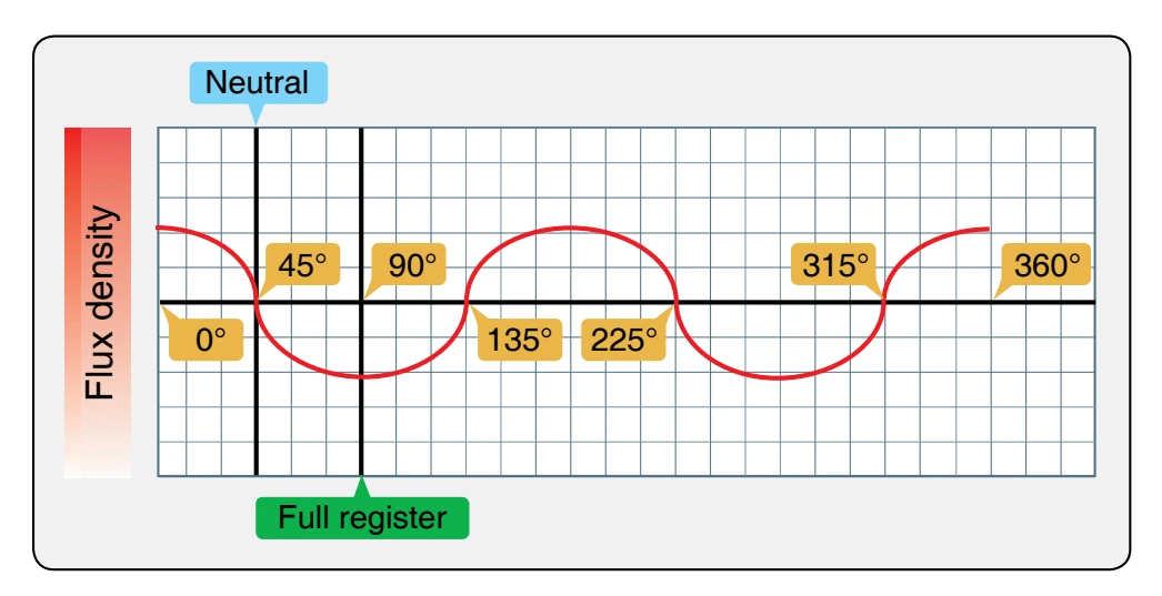
horizontal line. At the 90° position, another position of maximum flux is reached. Thus, for one revolution 360° of the four pole magnet, there are four positions of maximum flux, four positions of zero flux, and four flux reversals.
This discussion of the magnetic circuit demonstrates how the coil core is affected by the rotating magnet. It is subjected to an increasing and decreasing magnetic field and a change in polarity each 90° of magnet travel.
When a coil of wire as part of the magneto’s primary electrical circuit is wound around the coil core, it is also affected by the varying magnetic field.
Primary Electrical Circuit
The primary electrical circuit consists of a set of breaker contact points, a condenser, and an insulated coil. [Figure 4-5] The coil is made up of a few turns of heavy copper wire, one end is grounded to the coil core and the other end to the ungrounded side of the breaker points. [Figure 4-5] The primary circuit is complete only when the ungrounded breaker point contacts the grounded breaker point. The third unit in the circuit, the condenser (capacitor), is wired in parallel with the breaker points. The condenser prevents arcing at the points when the circuit is opened and hastens the collapse of the magnetic field about the primary coil.
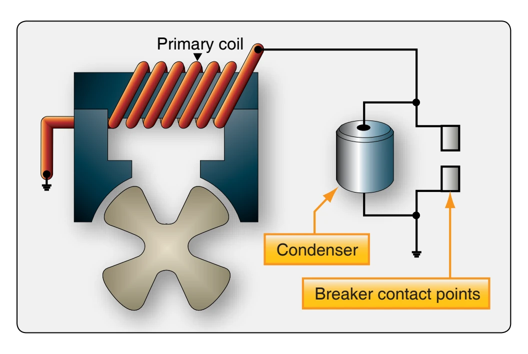
The primary breaker closes at approximately full register position. When the breaker points are closed, the primary electrical circuit is completed and the rotating magnet induces current flow in the primary circuit. This current flow generates its own magnetic field, which is in such a direction that it opposes any change in the magnetic flux of the permanent magnet’s circuit.
While the induced current is flowing in the primary circuit, it opposes any decrease in the magnetic flux in the core. This is in accordance with Lenz’s Law that states: “An induced current always flows in such a direction that its magnetism opposes the motion or the change that induced it.” (For a review of Lenz’s Law, refer to the Aviation Maintenance Technician—General Handbook, FAA-H-8083-30). Thus, the current flowing in the primary circuit holds the flux in the core at a high value in one direction until the rotating magnet has time to rotate through the neutral position to a point a few degrees beyond neutral. This position is called the E-gap position (E stands for efficiency).
There are three basic events required to fire a spark plug when its piston is in the prescribed position:
- the magneto must be in the E-gap position,
- the breaker contact points must be open, and
- the distributor must be aligned correctly.
With the magnetic rotor in E-gap position and the primary coil holding the magnetic field of the magnetic circuit in the opposite polarity, a very high rate of flux change can be obtained by opening the primary breaker points. Opening the breaker points stops the flow of current in the primary circuit and allows the magnetic rotor to quickly reverse the field through the coil core. This sudden flux reversal produces a high rate of flux change in the core, that cuts across the secondary coil of the magneto (wound over and insulated from the primary coil), inducing the pulse of high-voltage electricity in the secondary needed to fire a spark plug. As the rotor continues to rotate to approximately full register position, the primary breaker points close again and the cycle is repeated to fire the next spark plug in firing order. The sequence of events can now be reviewed in greater detail to explain how the state of extreme magnetic stress occurs.
With the breaker points, cam, and condenser connected in the circuit as shown in Figure 4-6, the action that takes place as the magnetic rotor turns is depicted by the graph curve in Figure 4-7. At the top (A) of Figure 4-7, the original static flux curve of the magnets is shown. Shown below the static flux curve is the sequence of opening and closing the magneto breaker points. Note that opening and closing the breaker points is timed by the breaker cam. The points close
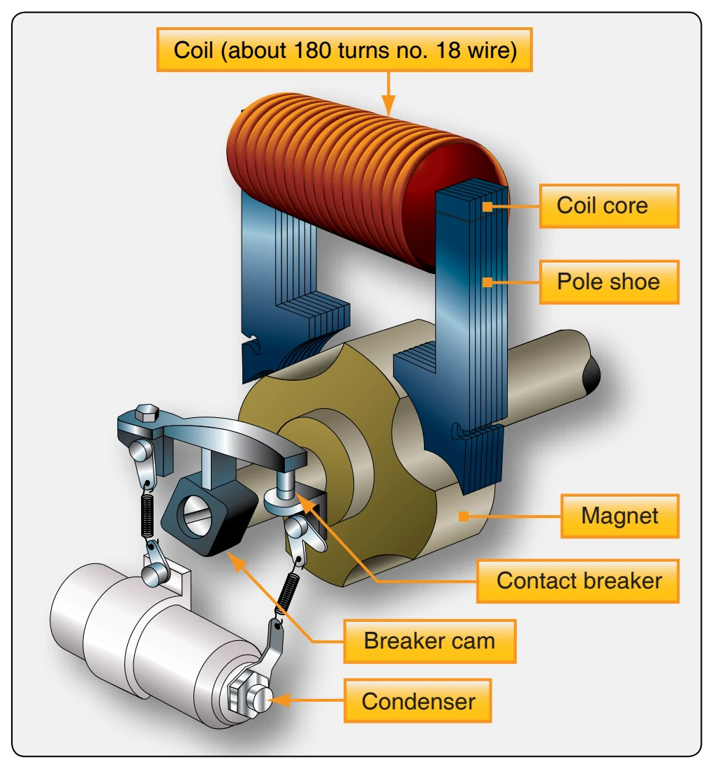
when a maximum amount of flux is passing through the coil core and open at a position after neutral. Since there are four lobes on this particular cam (there are some magnetos with cams that have only two lobes), the breaker points close and open in the same relation to each of the four neutral positions of the rotor magnet. Also, the point opening and point closing intervals are approximately equal.
Starting at the maximum flux position marked 0° at the top of Figure 4-7, the sequence of events in the following paragraphs occurs.
As the magnet rotor is turned toward the neutral position, the amount of flux through the core starts to decrease. [Figure 4-7D] This change in flux linkages induces a current in the primary winding. [Figure 4-7C] This induced current creates a magnetic field of its own that opposes the change of flux linkages inducing the current. Without current flowing in the primary coil, the flux in the coil core decreases to zero as the magnet rotor turns to neutral and starts to increase in the opposite direction (dotted static flux curve in Figure 4-7D). But, the electromagnetic action of the primary current prevents the flux from changing and temporarily holds the field instead of allowing it to change (resultant flux line in Figure 4-7D).