
Chapter 4
Engine Ignition & Electrical Systems
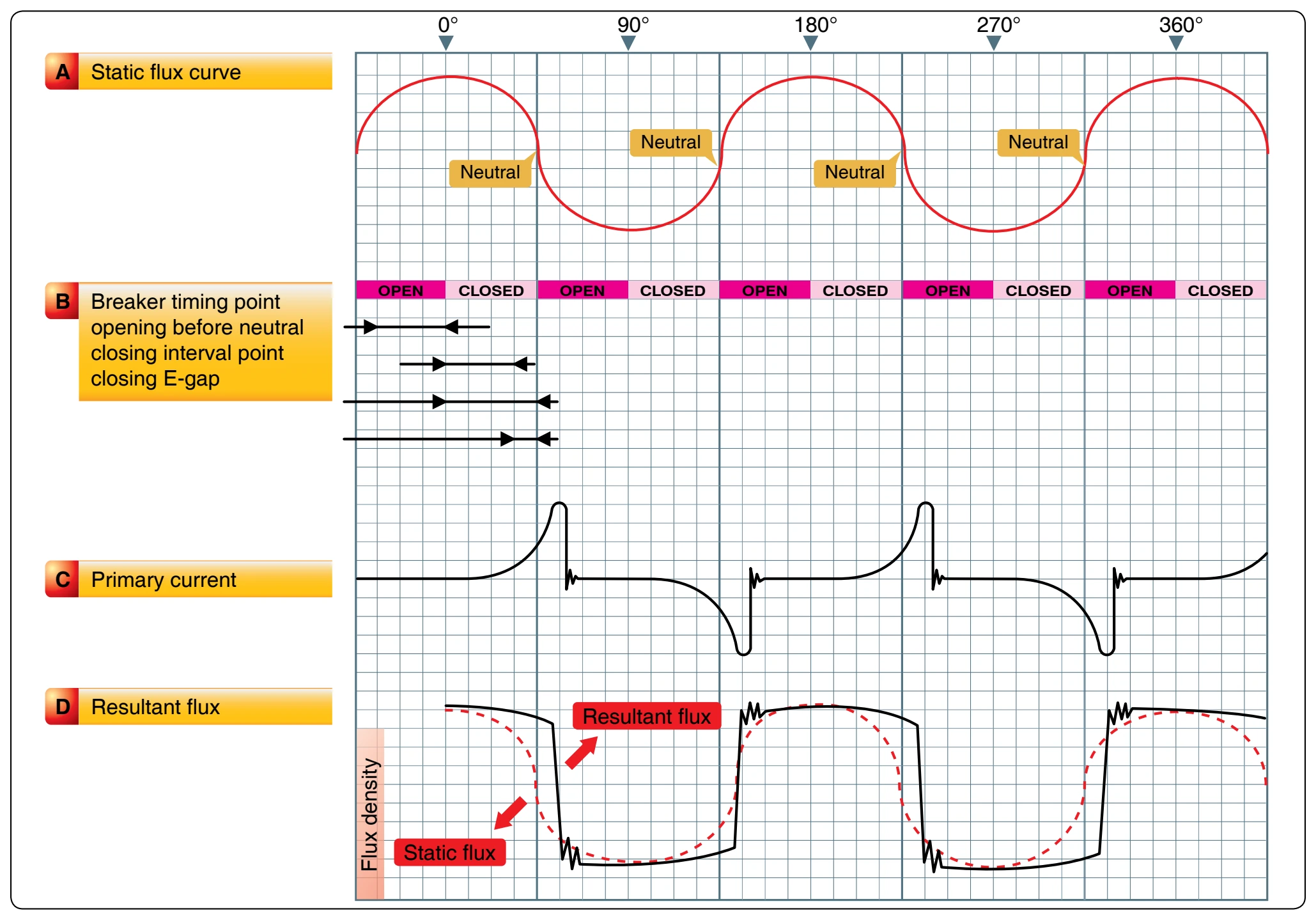
As a result of the holding process, there is a very high stress in the magnetic circuit by the time the magnet rotor has reached the position where the breaker points are about to open. The breaker points, when opened, function with the condenser to interrupt the flow of current in the primary coil, causing an extremely rapid change in flux linkages. The high-voltage in the secondary winding discharges across the gap in the spark plug to ignite the air-fuel mixture in the engine cylinder. Each spark actually consists of one peak discharge, after which a series of small oscillations takes place.
They continue to occur until the voltage becomes too low to maintain the discharge. Current flows in the secondary winding during the time that it takes for the spark to completely discharge. The energy or stress in the magnetic circuit is completely dissipated by the time the contacts close for the production of the next spark. Breaker assemblies, used in high-tension magneto-ignition systems, automatically open and close the primary circuit at the proper time in relation to piston position in the cylinder to which an ignition spark is being furnished. The interruption of the primary current flow is accomplished through a pair of breaker contact points made of an alloy that resists pitting and burning.
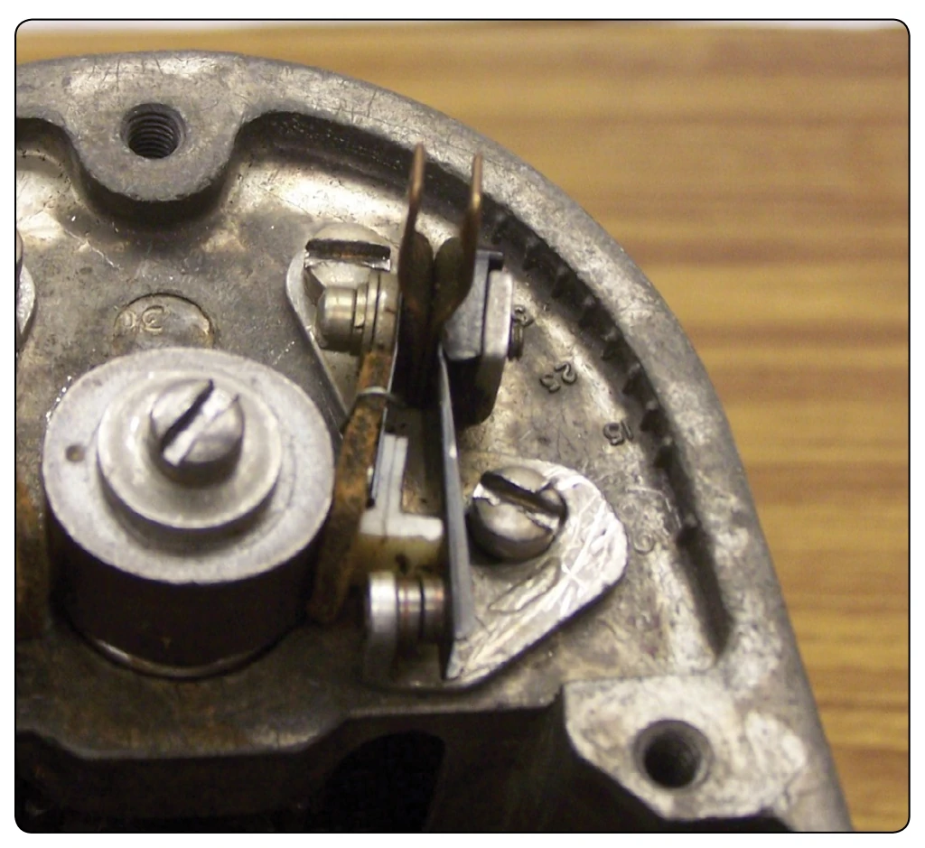
Most breaker points used in aircraft ignition systems are of the pivotless type in which one of the breaker points is movable and the other stationary. [Figure 4-8] The movable breaker point attached to the leaf spring is insulated from the magneto housing and is connected to the primary coil. [Figure 4-8] The stationary breaker point is grounded to the magneto housing to complete the primary circuit when the points are closed and can be adjusted so that the points can open at the proper time.
Another part of the breaker assembly is the cam follower, which is spring-loaded against the cam by the metal leaf spring. The cam follower is a Micarta block or similar material that rides the cam and moves upward to force the movable breaker contact away from the stationary breaker contact each time a lobe of the cam passes beneath the follower. A felt oiler pad is located on the underside of the metal spring leaf to lubricate and prevent corrosion of the cam.
The breaker-actuating cam may be directly driven by the magneto rotor shaft or through a gear train from the rotor shaft. Most large radial engines use a compensated cam that is designed to operate with a specific engine and has one lobe for each cylinder to be fired by the magneto. The cam lobes are machine ground at unequal intervals to compensate for the elliptical path of the articulated connecting rods. This path causes the pistons top dead center position to vary from cylinder to cylinder with regard to crankshaft rotation. A compensated 14-lobe cam, together with a two-, four-, and eight-lobe uncompensated cam, is shown in Figure 4-9.
The unequal spacing of the compensated cam lobes, although it provides the same relative piston position for ignition to occur, causes a slight variation of the E-gap position of the rotating magnet and thus a slight variation in the highvoltage impulses generated by the magneto. Since the spacing between each lobe is tailored to a particular cylinder of a particular engine, compensated cams are marked to show
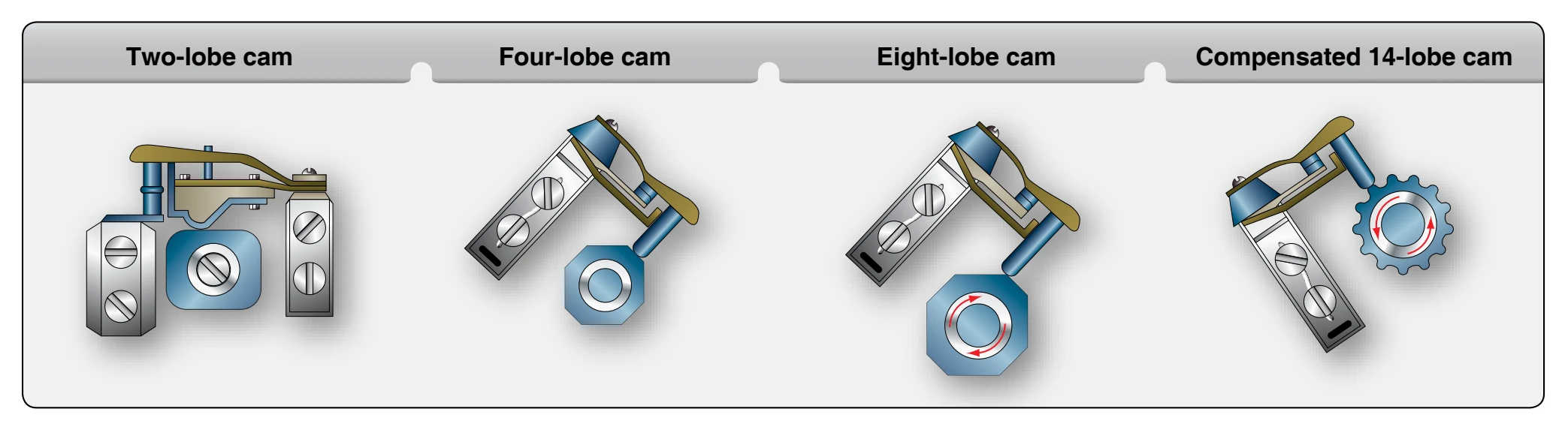
the series of the engine, the location of the master rods, the lobe used for magneto timing, the direction of cam rotation, and the E-gap specification in degrees past neutral of magnet rotation. In addition to these markings, a step is cut across the face of the cam, that, when aligned with scribed marks on the magneto housing, places the rotating magnet in the E-gap position for the timing cylinder. Since the breaker points should begin to open when the rotating magnet moves into the E-gap position, alignment of the step on the cam with marks in the housing provides a quick and easy method of establishing the exact E-gap position to check and adjust the breaker points.
Secondary Electrical Circuit
The secondary circuit contains the secondary windings of the coil, distributor rotor, distributor cap, ignition lead, and spark plug. The secondary coil is made up of a winding containing approximately 13,000 turns of fine, insulated wire; one end of which is electrically grounded to the primary coil or to the coil core and the other end connected to the distributor rotor. The primary and secondary coils are encased in a nonconducting material. The whole assembly is then fastened to the pole shoes with screws and clamps.
When the primary circuit is closed, the current flow through the primary coil produces magnetic lines of force that cut across the secondary windings, inducing an electromotive force. When the primary circuit current flow is stopped, the magnetic field surrounding the primary windings collapses, causing the secondary windings to be cut by the lines of force. The strength of the voltage induced in the secondary windings, when all other factors are constant, is determined by the number of turns of wire. Since most high-tension magnetos have many thousands of turns of wire in the secondary coil windings, a very high-voltage, often as high as 20,000 volts, is generated in the secondary circuit. The high-voltage induced in the secondary coil is directed to the distributor, which consists of two parts: revolving and stationary. The revolving part is called a distributor rotor and the stationary part is called a distributor block. The rotating part, which may take the shape of a disc, drum, or finger, is made of a non-conducting material with an embedded conductor. The stationary part consists of a block also made of non-conducting material that contains terminals and terminal receptacles into which the ignition lead wiring that connects the distributor to the spark plug is attached. This high-voltage is used to jump the air gap of electrodes of the spark plug in the cylinder to ignite the air-fuel mixture.
As the magnet moves into the E-gap position for the No. 1 cylinder and the breaker points just separate or open, the distributor rotor aligns itself with the No. 1 electrode in the distributor block. The secondary voltage induced as the breaker points open enters the rotor where it arcs a small air gap to the No. 1 electrode in the block.
Since the distributor rotates at one-half crankshaft speed on all four-stroke cycle engines, the distributor block has as many electrodes as there are engine cylinders, or as many electrodes as cylinders served by the magneto. The electrodes are located circumferentially around the distributor block so that, as the rotor turns, a circuit is completed to a different cylinder and spark plug each time there is alignment between the rotor finger and an electrode in the distributor block. The electrodes of the distributor block are numbered consecutively in the direction of distributor rotor travel. [Figure 4-10]
The distributor numbers represent the magneto sparking order rather than the engine cylinder numbers. The distributor electrode marked “1” is connected to the spark plug in the No. 1 cylinder; distributor electrode marked “2” to the second
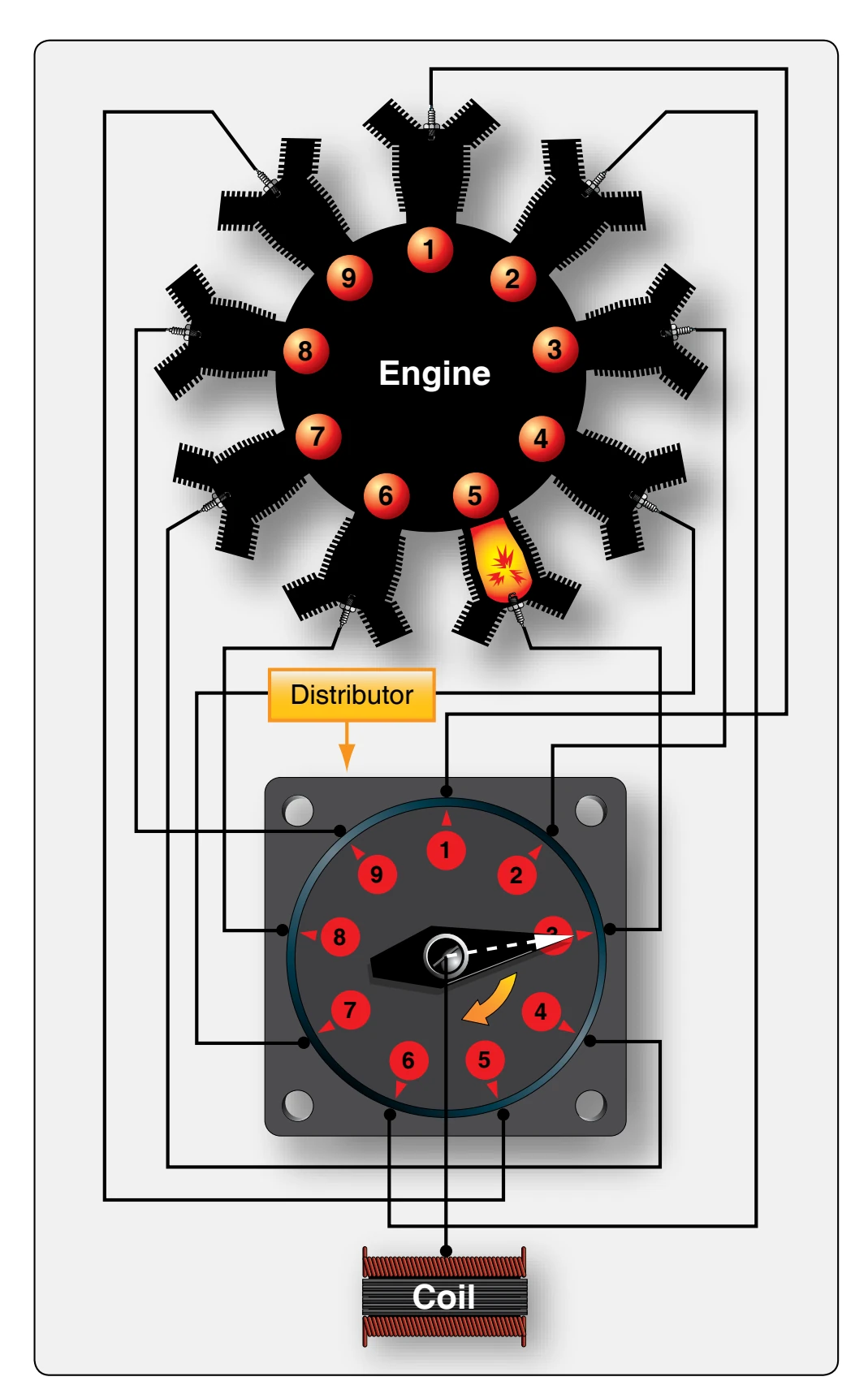
cylinder to be fired; distributor electrode marked “3” to the third cylinder to be fired, and so forth.
In Figure 4-10, the distributor rotor finger is aligned with the distributor electrode marked “3,” which fires the No. 5 cylinder of a nine-cylinder radial engine. Since the firing order of a nine-cylinder radial engine is 1-3-5-7-9-2-4-6-8, the third electrode in the magneto sparking order serves the No. 5 cylinder.