
Chapter 4
Engine Ignition & Electrical Systems
Since magneto and distributor assemblies are subjected to sudden changes in temperature, the problems of condensation and moisture are considered in the design of these units. Moisture in any form is a good conductor of electricity. If absorbed by the nonconducting material in the magneto, such as distributor blocks, distributor fingers, and coil cases, it can create a stray electrical conducting path. The high-voltage current that normally arcs across the air gaps of the distributor can flash across a wet insulating surface to ground, or the high-voltage current can be misdirected to some spark plug other than the one that should be fired. This condition is called flashover and usually results in cylinder misfiring. This can cause a serious engine condition called pre-ignition, which can damage the engine. For this reason, coils, condensers, distributors, and distributor rotors are waxed so that moisture on such units stand in separate beads and do not form a complete circuit for flashover.
Flashover can lead to carbon tracking, which appears as a fine pencil-like line on the unit across which flashover occurs. The carbon trail results from the electric spark burning dirt particles that contain hydrocarbon materials. The water in the hydrocarbon material is evaporated during flashover, leaving carbon to form a conducting path for current. When moisture is no longer present, the spark continues to follow the carbon track to the ground. This prevents the spark from getting to the spark plug, so the cylinder does not fire.
Magnetos cannot be hermetically sealed to prevent moisture from entering a unit, because the magneto is subject to pressure and temperature changes in altitude. Thus, adequate drains and proper ventilation reduce the tendency of flashover and carbon tracking. Good magneto circulation also ensures that corrosive gases produced by normal arcing across the distributor air gap, such as ozone, are carried away. In some installations, pressurization of the internal components of the magnetos and other various parts of the ignition system is essential to maintain a higher absolute pressure inside the magneto and to eliminate flashover due to high altitude flight. This type of magneto is used with turbocharged engines that operate at higher altitudes. Flashover becomes more likely at high altitudes because of the lower air pressure, which makes it easier for the electricity to jump air gaps. By pressurizing the interior of the magneto, the normal air pressure is maintained and the electricity or the spark is held within the proper areas of the magneto even though the ambient pressure is very low.
Even in a pressurized magneto, the air is allowed to flow through and out of the magneto housing. By providing more air and allowing small amounts of air to bleed out for ventilation, the magneto remains pressurized. Regardless of the method of venting employed, the vent bleeds or valves must be kept free of obstructions. Further, the air circulating through the components of the ignition system must be free of oil since even minute amounts of oil on ignition parts result in flashover and carbon tracking.
Ignition Harness
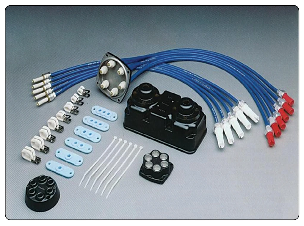
The ignition lead directs the electrical energy from the magneto to the spark plug. The ignition harness contains an insulated wire for each cylinder that the magneto serves in the engine. [Figure 4-11] One end of each wire is connected to the magneto distributor block and the other end is connected to the proper spark plug. The ignition harness leads serve a dual purpose. It provides the conductor path for the hightension voltage to the spark plug. It also serves as a shield for stray magnetic fields that surround the wires as they momentarily carry high-voltage current. By conducting these magnetic lines of force to the ground, the ignition harness cuts down electrical interference with the aircraft radio and other electrically sensitive equipment.
A magneto is a high frequency radiation emanating (radio wave) device during its operation. The wave oscillations produced in the magneto are uncontrolled and cover a wide range of frequencies and must be shielded. If the magneto and ignition leads were not shielded, they would form antennas and pick up the random frequencies from the ignition system.
The lead shielding is a metal mesh braid that surrounds the entire length of the lead. The lead shielding prevents the radiation of the energy into the surrounding area.
Capacitance is the ability to store an electrostatic charge between two conducting plates separated by a dielectric. Lead insulation is called a dielectric, meaning it can store electrical energy as an electrostatic charge. An example of electrostatic energy storage in a dielectric is the static electricity stored in a plastic hair comb. When shielding is placed around the ignition lead, capacitance increases by bringing the two plates closer together. Electrically, the ignition lead acts as a capacitor and has the ability to absorb and store electrical energy. The magneto must produce enough energy to charge the capacitance caused by the ignition lead and have enough energy left over to fire the plug.
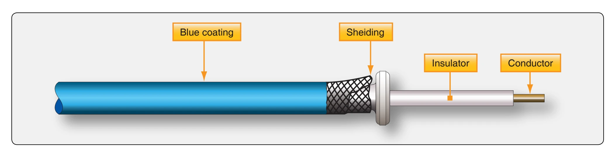
Ignition lead capacitance increases the electrical energy required to provide a spark across the plug gap. More magneto primary current is needed to fire the plug with the shielded lead. This capacitance energy is discharged as fire across the plug gap after each firing of the plug. Reversing the polarity during servicing by rotating the plugs to new locations, the plug wear is equalized across the electrodes. The very center of the ignition lead is the high-voltage carrier surrounded by a silicone insulator material that is surrounded by a metal mesh, or shielding, covered with a thin silicone rubber coating that prevents damage by engine heat, vibration, or weather.
A sectional view of the typical ignition lead is shown in Figure 4-12. Ignition leads must be routed and clamped correctly to avoid hot spots on the exhaust and vibration points as the leads are routed from the magneto to the individual cylinders. Ignition leads are normally of the all-weather type and are hard connected at the magneto distributor and affixed to the spark plug by threads. The shielded ignition lead spark plug terminal is available in allweather ¾ inch diameter and 5⁄ inch diameter barrel ignition 8 lead nut. [Figure 4-13] The 5⁄ – 24 plug takes a ¾ wrench 8 on the lead nut and the ¾ – 20 plug takes a 7⁄ wrench on the 8 lead nut. The ¾ inch all-weather design utilizes a terminal seal that results in greater terminal well insulation. This
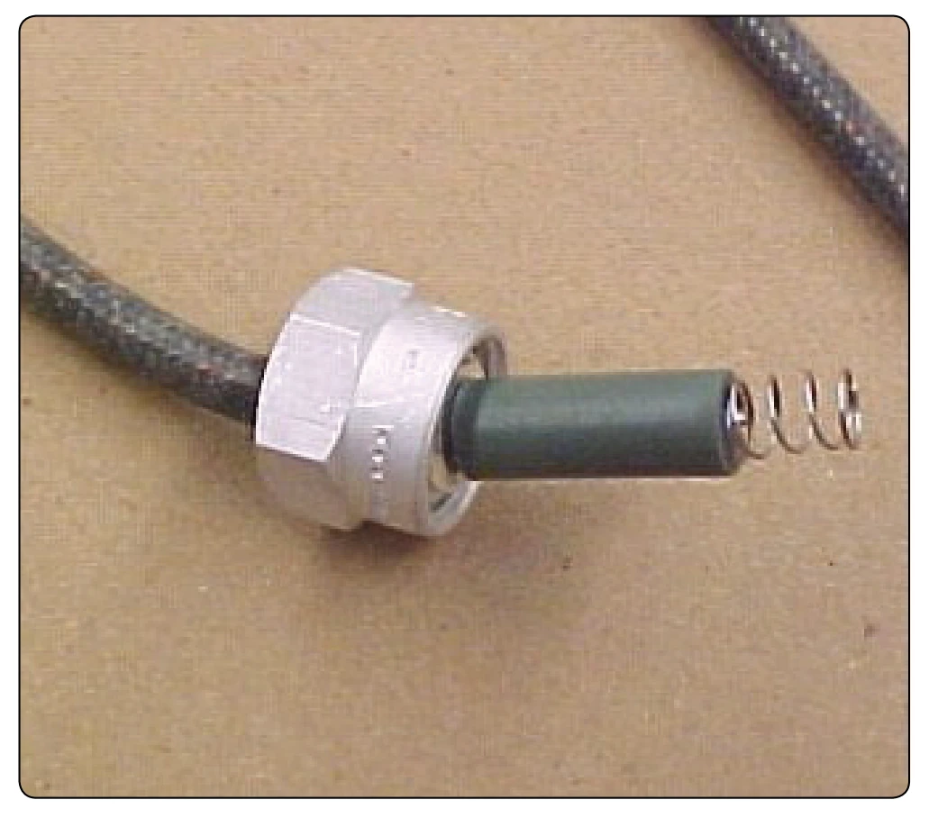
is recommended because the lead end of the spark plug is completely sealed from moisture.
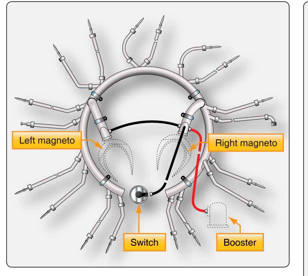
An older radial engine type of ignition harness is a manifold formed to fit around the crankcase of the engine with flexible extensions terminating at each spark plug. A typical hightension ignition harness is shown in Figure 4-14. Many older single-row radial engine aircraft ignition systems employ a dual-magneto system, in which the right magneto supplies the electric spark for the front plugs in each cylinder, and the left magneto fires the rear plugs.
Ignition Switches
All units in an aircraft ignition system are controlled by an ignition switch. The type of switch used varies with the number of engines on the aircraft and the type of magnetos used. All switches, however, turn the system off and on in much the same manner. The ignition switch is different in at least one respect from all other types of switches: when the ignition switch is in the off position, a circuit is completed through the switch to ground. In other electrical switches, the off position normally breaks or opens the circuit.
The ignition switch has one terminal connected to the primary electrical circuit between the coil and the breaker contact points. The other terminal of the switch is connected to the aircraft ground structure. As shown in Figure 4-15, two ways to complete the primary circuit are: