
Chapter 4
Engine Ignition & Electrical Systems
Conductor length correction - intermittent flow chart
Linear form: L2 = (254.5 × L1) / (234.5 + T2)
designed to do a specific job.
The type of conductor insulation material varies with the type of installation. Rubber, silk, and paper insulation are no longer used extensively in aircraft systems. More common today are such materials as vinyl, cotton, nylon, Teflon, and Rockbestos.
Identifying Wire & Cable
To aid in testing and repair operations, many maintenance activities mark wire or cable with a combination of letters and numbers that identify the wire, the circuit it belongs to, the gauge number, and other information necessary to relate the wire or cable to a wiring diagram. Such markings are the identification code.
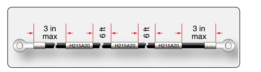
There is no standard procedure for marking and identifying wiring; each manufacturer normally develops its own identification code. Figure 4-88 illustrates one identification system and shows the usual spacing in marking a wire. Some system components, especially plugs and jacks, are identified by a letter or group of letters and numbers added to the basic identification number. These letters and numbers may indicate the location of the component in the system. Interconnected cables are also marked in some systems to indicate location, proper termination, and use. In any system, the marking should be legible, and the stamping color should contrast with the color of the wire insulation. For example, use black stamping with light-colored backgrounds, or white stamping on dark-colored backgrounds.
Most manufacturers mark the wires at intervals of not more than 15 inches lengthwise and within 3 inches of each junction or terminating point. [Figure 4-89] Coaxial cable and wires at terminal blocks and junction boxes are often identified by marking or stamping a wiring sleeve rather than the wire itself. For general purpose wiring, flexible vinyl sleeving, either clear or white opaque, is
commonly used. For high-temperature applications, silicone rubber or silicone fiberglass sleeving is recommended. Where resistance to synthetic hydraulic fluids or other solvents is necessary, either clear or white opaque nylon sleeving can be used.
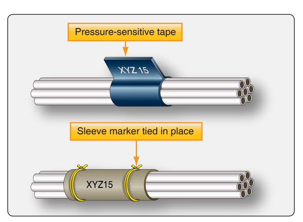
While the preferred method is to stamp the identification marking directly on the wire or on sleeving, other methods are often employed. One method uses a marked sleeve tied in place. The other uses a pressure-sensitive tape. [Figure 4-90]
Electrical Wiring Installation
The following recommended procedures for installing aircraft electrical wiring are typical of those used on most types of aircraft. For purposes of this discussion, the following definitions are applicable:
- Open wiring—any wire, wire group, or wire bundle not enclosed in conduit.
- Wire group—two or more wires in the same location, tied together to identity the group.
- Wire bundle—two or more wire groups tied together because they are going in the same direction at the point where the tie is located. The bundle facilitates maintenance.
- Electrically protected wiring—wires that include in the circuit protections against overloading, such as fuses, circuit breakers, or other limiting devices.
- Electrically unprotected wiring—wires, generally from generators to main bus distribution points, that
do not have protection, such as fuses, circuit breakers, or other current-limiting devices.
Wire Groups & Bundles
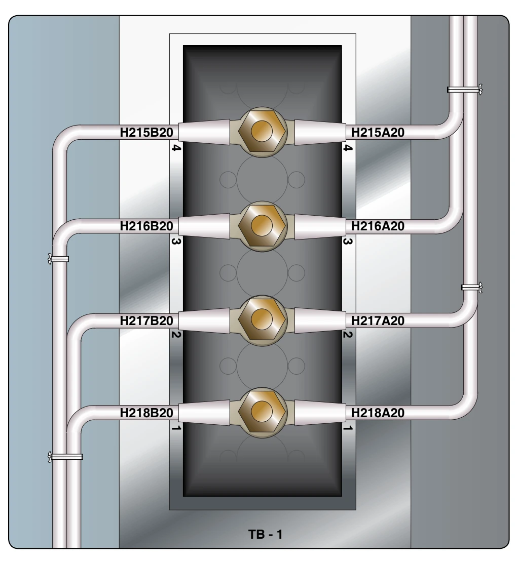
Grouping or bundling certain wires, such as electrically unprotected power wiring and wiring to duplicate vital equipment, should be avoided. Wire bundles should generally be limited in size to a bundle of 75 wires, or 2 inches in diameter where practicable. When several wires are grouped at junction boxes, terminal blocks, panels, etc., the identity of the group within a bundle can be retained. [Figure 4-91]
Twisting Wires
When specified on the engineering drawing, parallel wires must be twisted. The most common examples are: