
Chapter 4
Engine Ignition & Electrical Systems
Wire Size
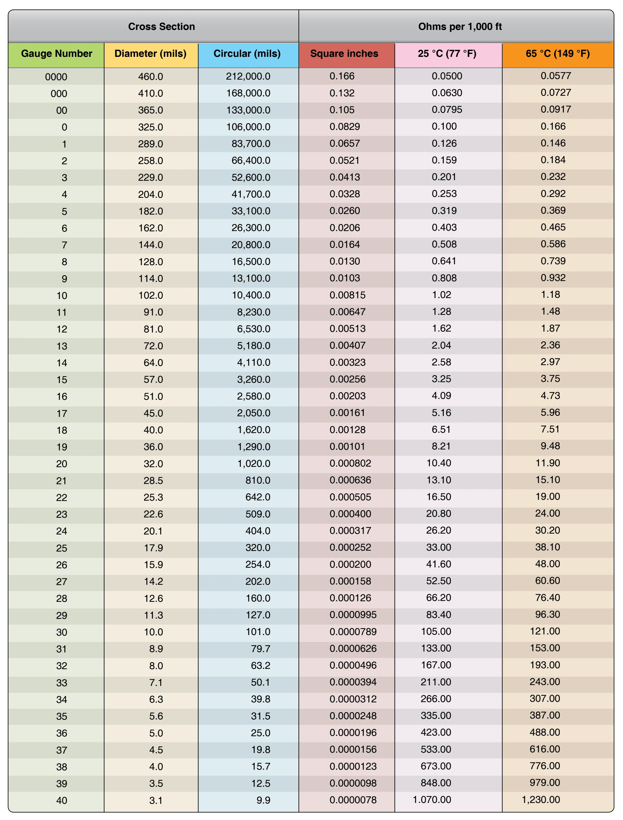
Wire is manufactured in sizes according to a standard known as the American wire gauge (AWG). The wire diameters become smaller as the gauge numbers become larger. The largest wire size shown in Figure 4-81 is number 0000,
and the smallest is number 40. Larger and smaller sizes are manufactured but are not commonly used.
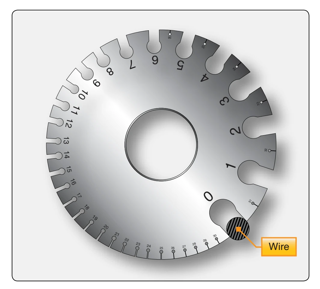
Wire size may be determined by using a wire gauge. [Figure 4-82] This type of gauge measures wires ranging in size from number 0 (zero) to number 36. The wire to be measured is inserted in the smallest slot that just accommodates the bare wire. The gauge number corresponding to that slot indicates the wire size. The slot has parallel sides and should not be confused with the semicircular opening at the end of the slot. The opening simply permits the free movement of the wire all the way through the slot.
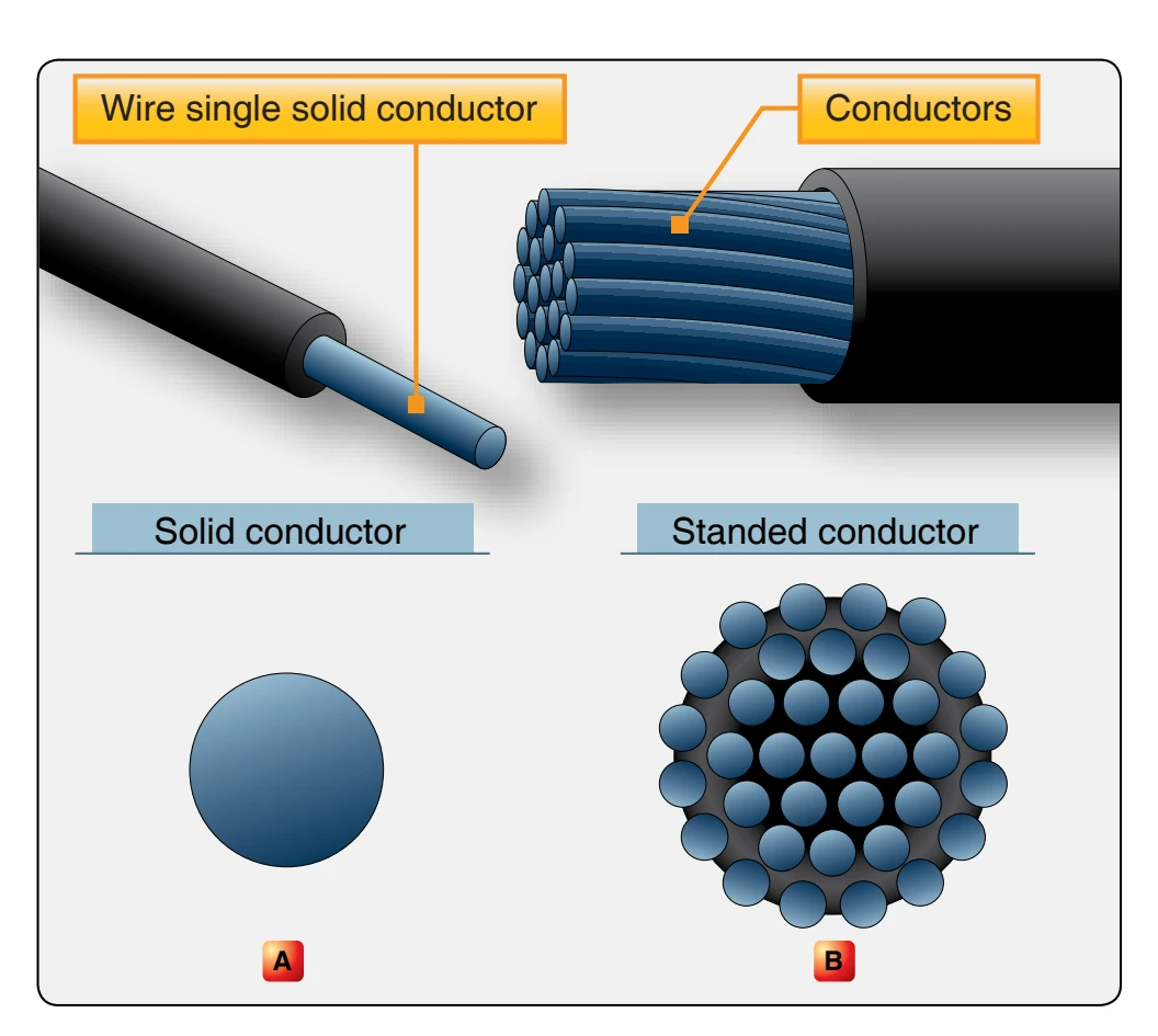
Gauge numbers are useful in comparing the diameter of wires, but not all types of wire or cable can be accurately measured with a gauge. Large wires are usually stranded to increase their flexibility. In such cases, the total area can be determined by multiplying the area of one strand, usually computed in circular mils (commonly used as a reference to wire size) when diameter or gauge number is known by the number of strands in the wire or cable.
Factors Affecting the Selection of Wire Size
Several factors must be considered in selecting the size of wire for transmitting and distributing electric power. One factor is the allowable power loss (PR loss) in the line. This loss represents electrical energy converted into heat. The use of large conductors reduces the resistance and therefore the PR loss. However, large conductors are more expensive initially than small ones; they are heavier and require more substantial supports.
A second factor is the permissible voltage drop (IR drop) in the line. If the source maintains a constant voltage at
the input to the line, any variation in the load on the line causes a variation in line current and a consequent variation in the IR drop in the line. A wide variation in the IR drop in the line causes poor voltage regulation at the load. The obvious remedy is to reduce either current or resistance. A reduction in load current lowers the amount of power being transmitted, whereas a reduction in line resistance increases the size and weight of conductors required. A compromise is generally reached whereby the voltage variation at the load is within tolerable limits and the weight of line conductors is not excessive.
A third factor is the current carrying ability of the conductor. When current is drawn through the conductor, heat is generated. The temperature of the wire rises until the heat radiated, or otherwise dissipated, is equal to the heat generated by the passage of current through the line. If the conductor is insulated, the heat generated in the conductor is not so readily removed as it would be if the conductor were not insulated. Thus, to protect the insulation from too much heat, the current through the conductor must be maintained below a certain value.
When electrical conductors are installed in locations where the ambient temperature is relatively high, the heat generated by external sources constitutes an appreciable part of the total conductor heating. Allowance must be made for the influence of external heating on the allowable conductor current, and each case has its own specific limitations. The maximum allowable operating temperature of insulated conductors varies with the type of conductor insulation being used.
Tables are available that list the safe current ratings for various sizes and types of conductors covered with various types of insulation. The chart in Figure 4-83 shows the current carrying capacity and resistance of copper wire continuous duty wire in bundles at various temperature ratings.
Factors Affecting Selection of Conductor Material
Although silver is the best conductor, its cost limits its use to special circuits where a substance with high conductivity is needed. The two most generally used conductors are copper and aluminum. Each has characteristics that make its use advantageous under certain circumstances; also, each has certain disadvantages.
Copper has a higher conductivity; it is more ductile, can be drawn out, has relatively high tensile strength, and can be easily soldered. It is more expensive and heavier than aluminum.
Although aluminum has only about 60 percent of the conductivity of copper, it is used extensively. Its light weight makes possible long spans, and its relatively large diameter for a given conductivity reduces corona, the discharge of electricity from the wire when it has a high potential. The discharge is greater when smaller diameter wire is used than when larger diameter wire is used. Some bus bars are made of aluminum which has a greater radiating surface than copper for the same conductance. The characteristics of copper and aluminum are compared in Figure 4-84.