Chapter 5
Engine Starting Systems
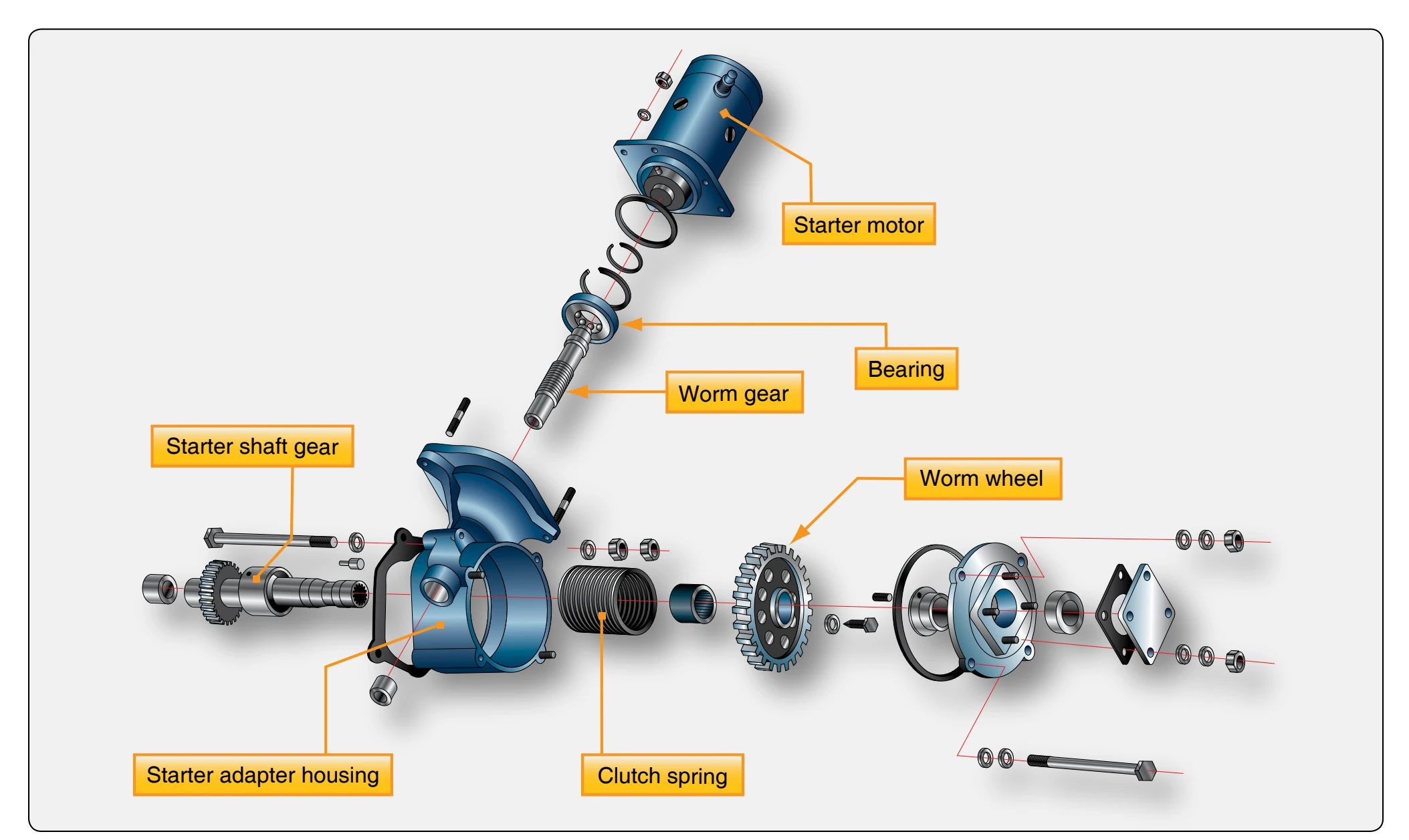
Some engines incorporate an automatic starting system that employs an electric starter motor mounted on a right angle drive adapter. As the starter motor is electrically energized, the adapter worm shaft and gear engage the starter shaft gear by means of a spring and clutch assembly. The shaft gear, in turn, rotates the crankshaft. When the engine begins to turn on its own power, the clutch spring disengages from the shaft gear. The starter adapter uses a worm drive gear shaft and worm gear to transfer torque from the starter motor to the clutch assembly. [Figure 5-9] As the worm gear rotates the worm wheel and clutch spring, the clutch spring is tightened around the drum of the starter shaft gear. As the shaft gear turns, torque is transmitted directly to the crankshaft gear.
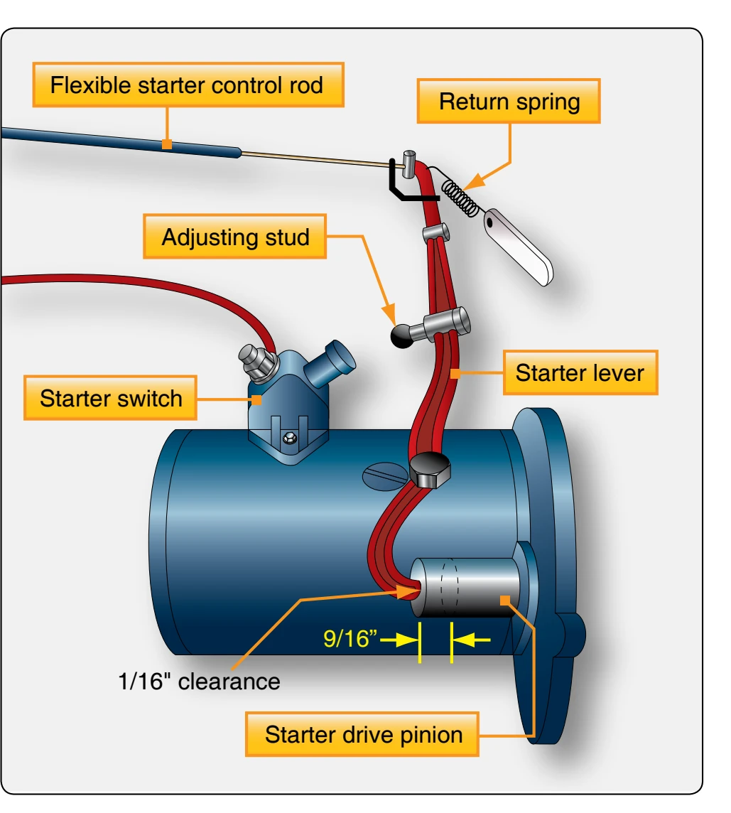
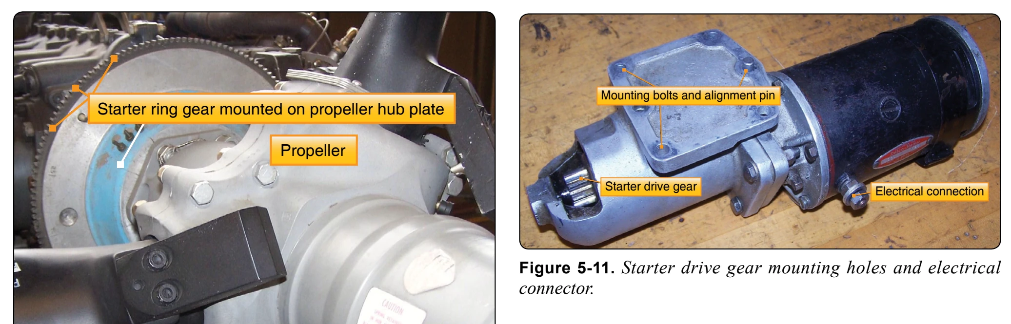
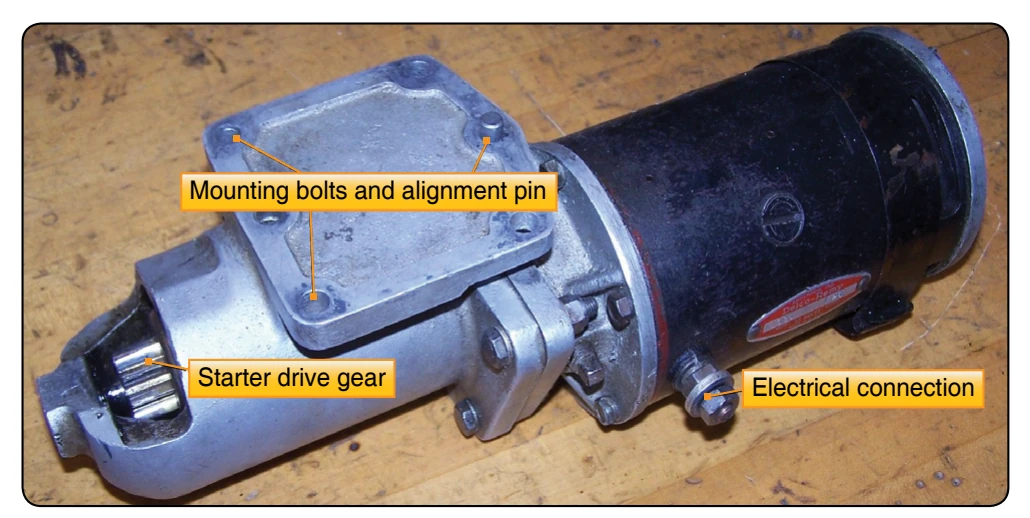
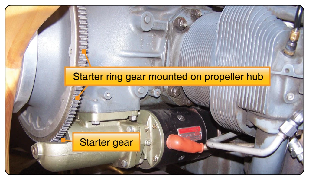
Other engines use a starter that drives a ring gear mounted to the propeller hub. [Figure 5-10] It uses an electric motor and a drive gear that engages as the motor is energized and spins the gear, which moves out and engages the ring gear on the propeller hub cranking the engine for start. [Figure 5-11] As the engine starts, the starter drive gear is spun back by the engine turning, which disengages the drive gear. [Figure 5-12] The starter motors on small aircraft also have operational limits with cool down times that should be observed.
Reciprocating Engine Starting System Maintenance Practices
Most starting system maintenance practices include replacing the starter motor brushes and brush springs, cleaning dirty commutators, and turning down burned or out-of-round
Roughness, out-of-roundness, or high-mica conditions are reasons for turning down the commutator. In the case of a high-mica condition, the mica should be undercut after the starter commutators. As a rule, starter brushes should be replaced when worn down to approximately one-half the original length. Brush spring tension should be sufficient to give brushes a good firm contact with the commutator. Brush leads should be unbroken and lead terminal screws tight.
A glazed or dirty starter commutator can be cleaned by holding a strip of double-0 sandpaper or a brush seating stone against the commutator as it is turned. The sandpaper or stone should be moved back and forth across the commutator to avoid wearing a groove. Emery paper or carborundum should never be used for this purpose because of their possible shorting action.
turning operation is accomplished. Refer to FAA-H-8083-30, Aviation Maintenance Technician—General for a review of high-mica commutators in motors.
The drive gear should be checked for wear along with the ring gear. The electrical connections should be checked for looseness and corrosion. Also, check the security of the mounting of the housing of the starter.
Troubleshooting Small Aircraft Starting Systems
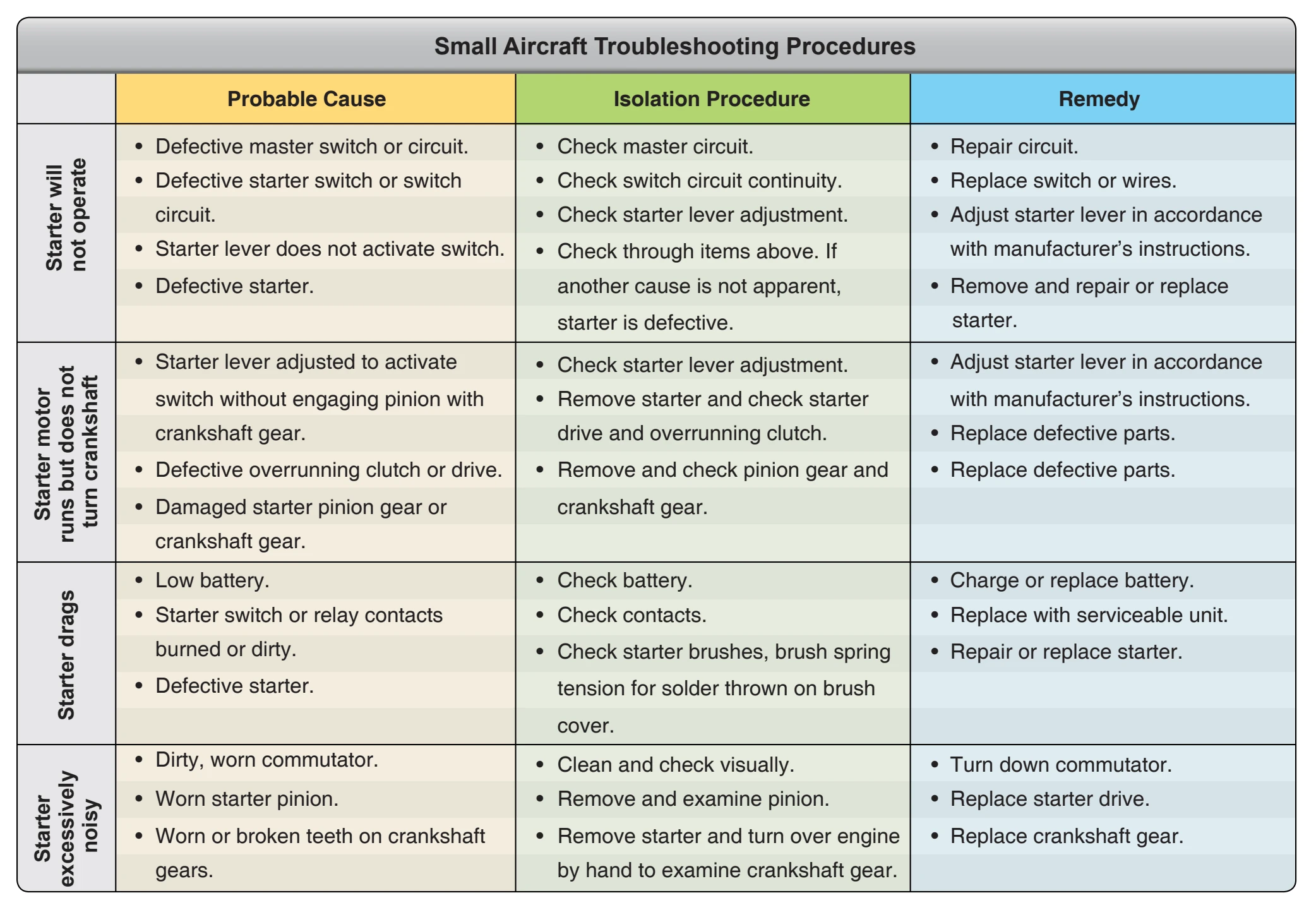
The troubleshooting procedures listed in Figure 5-13 are typical of those used to isolate malfunctions in small aircraft starting systems.
Gas Turbine Engine Starters
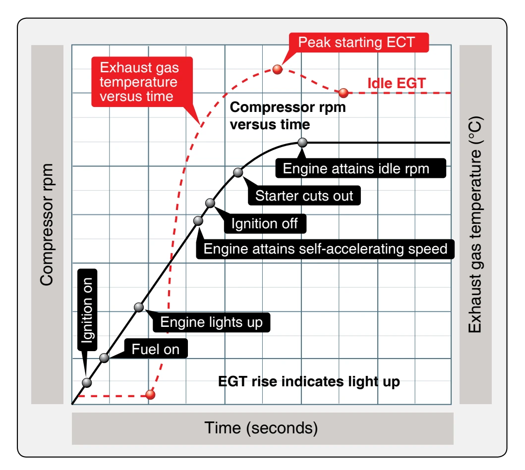
Gas turbine engines are started by rotating the high-pressure compressor. On dual-spool, axial flow engines, the highpressure compressor and N1 turbine system is only rotated by the starter. To start a gas turbine engine, it is necessary to accelerate the compressor to provide sufficient air to support combustion in the combustion section, or burners. Once ignition and fuel have been introduced and the lite-off has occurred, the starter must continue to assist the engine until the engine reaches a self-sustaining speed. The torque supplied by the starter must be in excess of the torque required to overcome compressor inertia and the friction loads of the engine’s compressor.
Figure 5-14 illustrates a typical starting sequence for a gas turbine engine, regardless of the type of starter employed. As soon as the starter has accelerated the compressor sufficiently to establish airflow through the engine, the ignition is turned on followed by the fuel. The exact sequence of the starting procedure is important since there must be sufficient airflow through the engine to support combustion before the air-fuel mixture is ignited. At low engine cranking speeds, the fuel flow rate is not sufficient to enable the engine to accelerate; for this reason, the starter continues to crank the engine until after self-accelerating speed has been attained. If assistance from the starter were cut off below the self-accelerating speed, the engine would either fail to accelerate to idle speed or might even decelerate because it could not produce sufficient energy to sustain rotation or to accelerate during the initial phase of the starting cycle. The starter must continue to assist the engine considerably above the self-accelerating speed to avoid a delay in the starting cycle, which would result in a hot or hung false start or a combination of both. At the proper points in the sequence, the starter and ignition