
Chapter 6
Lubrication & Cooling Systems
Breather Pressurizing System
The breather pressurizing system ensures a proper oil spray pattern from the main bearing oil jets and furnishes a pressure head to the scavenge system. Breather tubes in the compressor inlet case, the oil tank, the diffuser case, and the turbine exhaust case are connected to external tubing at the top of the engine. By means of this tubing, the vapor-laden atmospheres of the various bearing compartments and the oil tank are brought together in the deoiler in the accessory gearbox. The deoiler separates out the oil from the air-oil mist and vents the air back to the atmosphere.
Typical Dry-Sump Variable Pressure Lubrication System
The dry-sump variable-pressure lubrication system uses the same basic subsystems that the regulated systems use (pressure Scavenge breather). [Figure 6-46] The main difference is that the pressure in this system is not regulated by a regulating bypass valve. Most large turbofan engine pressure systems are variable-pressure systems in which the pump outlet pressure (oil pressure) depends on the engine rpm. In other words, the pump output pressure is proportional to the engine speed. Since the resistance to flow in the system does not vary much during operation and the pump has only the variable of turning faster or slower, the pressure is a function of engine speed. As an example, oil pressure can vary widely in this type of system, from 100 psi to over 260 psi, with the relief valve opening at about 540 psi.
Pressure Subsystem
The oil flows from the oil tank down to the pressure stage of the oil pump. A slight pressure in the tank assures that the flow of oil into the pressure pump is continuous. After being pressurized, it moves on to the oil filter where it is filtered. If the filter is clogged, the bypass valve sends the oil around the filter. There is no regulating valve but there is a relief valve to prevent the system pressure from exceeding the maximum limits. This valve is usually set to open well above the system’s operating pressure. The oil flows from the filter housing to the engine air-oil cooler. The oil either bypasses the cooler (cold) or passes through the cooler (hot) and then on to the fuel-oil cooler. Through the use of the coolers, the fuel temperature is adjusted to meet the requirements needed for the engine. Some of the oil passes through the classified
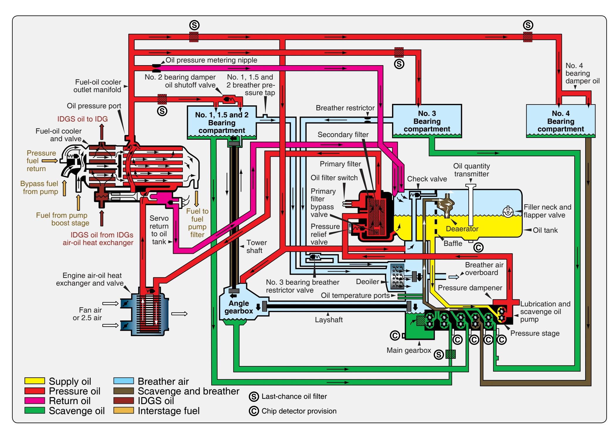
oil pressure trim orifice that helps adjust oil pressure at low speeds. The oil now flows through the last-chance oil filters (strainers) that remove particles from the oil if the oil filter has been bypassed. The engine oil passes through the nozzles to lubricate the bearings, gearboxes, seals, and accessory drive splines. After performing its functions of lubricating, cleaning, and cooling the bearings, the oil needs to be returned to the old tank by the scavenge system.
Scavenger Subsystem
The scavenger oil pump has several stages that pull oil from the bearing compartments and gearboxes and sends the oil to the tank. At the tank, the oil enters the deaerator, which separates the air from the scavenge oil. The oil returns to the tank and the air is vented through a check valve overboard. Each stage of the scavenge pump has a magnetic chip detector that can be removed for inspection.
Breather Subsystem
The purpose of the breather system is to remove air from the bearing compartments, separate breather air from oil, and vent the air overboard. The breather air from the bearing compartments is drawn to the gearbox by the deoiler. The deoiler is turned at high speed and causes the oil to separate from the air. The air is then vented with air from the deaerator overboard. By referring to Figure 6-46, notice that the deaerator is in the oil tank and the deoiler is in the main gearbox.
Turbine Engine Wet-Sump Lubrication System
In some engines, the lubrication system is the wet-sump type. There are relatively few engines using a wet-sump type of oil system. The components of a wet-sump system are similar to those of a dry-sump system. The major difference between the two systems is the location of the oil reservoir. The reservoir for the wet-sump oil system may be the accessory gear case or it may be a sump mounted on the bottom of the accessory case. Regardless of configuration, reservoirs for wet-sump systems are an integral part of the engine and contain the bulk of the engine oil supply. [Figure 6-47]
Included in the wet-sump reservoir are the following components:
- A sight gauge indicates the oil level in the sump.
- A vent or breather equalizes pressure within the accessory casing.
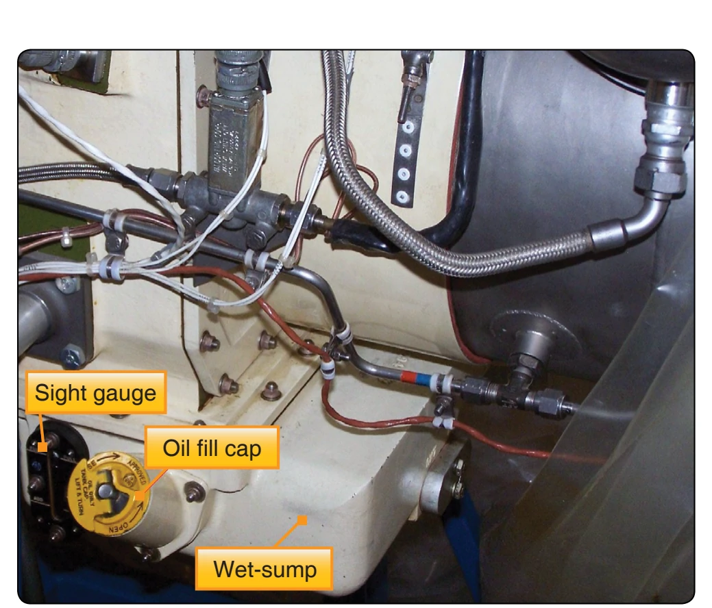
- A magnetic drain plug may be provided to drain the oil and also to trap any ferrous metal particles in the oil. This plug should always be examined closely during inspections. The presence of metal particles may indicate gear or bearing failure.
- Provision may also be made for a temperature bulb and an oil pressure fitting.
This system is typical of all engines using a wet-sump lubrication system. The bearing and drive gears in the accessory drive casing are lubricated by a splash system. The oil for the remaining points of lubrication leaves the pump under pressure and passes through a filter to jet nozzles that direct the oil into the rotor bearings and couplings. The oil is returned to the reservoir (sump) by gravity. Oil from the compressor bearing and the accessories drive coupling shaft drains directly into the reservoir. Turbine oil drains into a sump where the oil was originally pumped.