
Chapter 7
Propellers
Metal propellers and blades are generally susceptible to fatigue failure resulting from the concentration of stresses at the bottoms of sharp nicks, cuts, and scratches. It is necessary, therefore, to frequently and carefully inspect them for such defects and make repairs promptly. The inspection of steel blades may be accomplished by either visual, fluorescent penetrant or magnetic particle inspection. The visual inspection is easier if the steel blades are covered with engine oil or rust-preventive compound. The full length of the leading edge (especially near the tip), the full length of the trailing edge, the grooves and shoulders on the shank, and all dents and scars should be examined with a magnifying glass to decide whether defects are scratches or cracks.
Tachometer inspection is a very important part of the overall propeller inspection. Operation with an inaccurate tachometer may result in restricted rpm operation and damaging high stresses. This could shorten blade life and could result in catastrophic failure. If the tachometer is inaccurate, then the propeller could be turning much faster than it is rated to turn, providing extra stress. Accuracy of the engine tachometer should be verified at 100-hour intervals or at annual inspection, whichever occurs first. Hartzell Propeller recommends using a tachometer that is accurate within ± 10 rpm and has an appropriate calibration schedule.
Aluminum Propeller Inspection
Carefully inspect aluminum propellers and blades for cracks and other flaws. A transverse crack or flaw of any size is cause for rejection. No repairs are permitted to the shanks (roots or hub ends) of aluminum-alloy, adjustable-pitch blades. The shanks must be within manufacturer’s limits. Multiple deep nicks and gouges on the leading edge and face of the blade is cause for rejection. Use dye penetrant or fluorescent dye penetrant to confirm suspected cracks found in the propeller. Refer any unusual condition or appearance revealed by these inspections to the manufacturer.
Composite Propeller Inspection
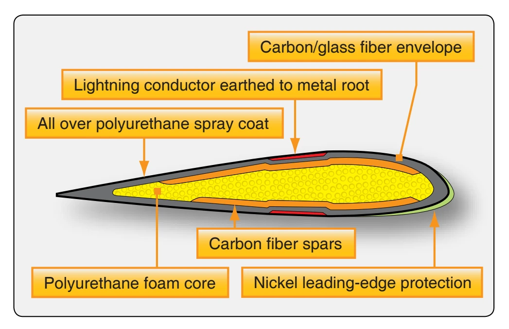
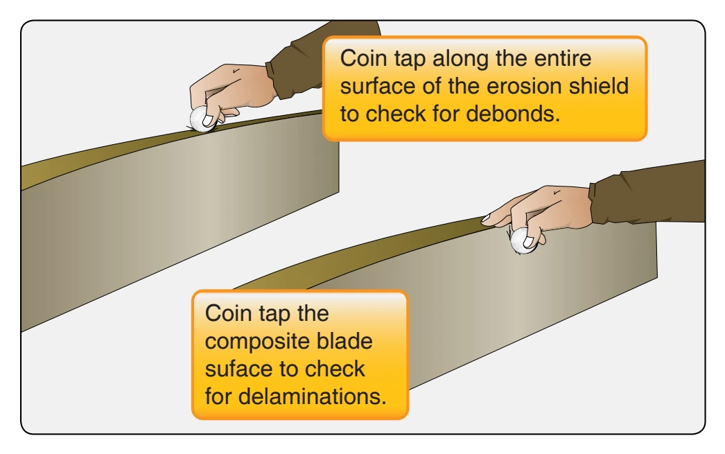
Composite blades need to be visually inspected for nicks, gouges, loose material, erosion, cracks and debonds, and lightning strike. [Figure 7-32] Composite blades are inspected for delaminations and debonds by tapping the blade or cuff (if applicable) with a metal coin. If an audible change is apparent, sounding hollow or dead, a debond or delamination is likely. [Figure 7-33] Blades that incorporate a “cuff” have a different tone when coin tapped in the cuff area. To avoid confusing the sounds, coin tap the cuff area and the transition area between the cuff and the blade separately from the blade area. Additional nondestructive testing (NDT) techniques for composite materials, such as phased array inspections, and ultrasound inspections, are available for more detailed inspections.
Repairs to propellers are often limited to minor type repairs. Certificated mechanics are not allowed to perform major repairs on propellers. Major repairs need to be accomplished by a certificated propeller repair station.
Propeller Vibration
Although vibration can be caused by the propeller, there are numerous other possible sources of vibration that can make troubleshooting difficult. If a propeller vibrates, whether due to balance, angle, or track problems, it typically vibrates throughout the entire rpm range, although the intensity of the vibration may vary with the rpm. If a vibration occurs only at one particular rpm or within a limited rpm range (e.g., 2200– 2350 rpm), the vibration is not normally a propeller problem but a problem of a poor engine-propeller match. If a propeller vibration is suspected but cannot be positively determined, the ideal troubleshooting method is to temporarily replace the propeller with one known to be airworthy and then test fly the aircraft if possible. Blade shake is not the source of vibration problems. Once the engine is running, centrifugal force holds the blades firmly (approximately 30,000–40,000 pounds) against blade bearings. Cabin vibration can sometimes be improved by reindexing the propeller to the crankshaft. The propeller can be removed, rotated 180°, and reinstalled. The propeller spinner can be a contributing factor to an out-ofbalance condition. An indication of this would be a noticeable spinner wobble while the engine is running. This condition is usually caused by inadequate shimming of the spinner front support or a cracked or deformed spinner.
When powerplant vibration is encountered, it is sometimes difficult to determine whether it is the result of engine vibration or propeller vibration. In most cases, the cause of the vibration can be determined by observing the propeller hub, dome, or spinner while the engine is running within a 1,200- to 1,500-rpm range and determining whether or not the propeller hub rotates on an absolutely horizontal plane. If the propeller hub appears to swing in a slight orbit, the vibration is usually caused by the propeller. If the propeller hub does not appear to rotate in an orbit, the difficulty is probably caused by engine vibration.
When propeller vibration is the reason for excessive vibration, the difficulty is usually caused by propeller blade imbalance, propeller blades not tracking, or variation in propeller blade angle settings. Check the propeller blade tracking and then the low-pitch blade angle setting to determine if either is the cause of the vibration. If both propeller tracking and low blade angle setting are correct, the propeller is statically or dynamically unbalanced and should be replaced, or rebalanced if permitted by the manufacturer.
Blade Tracking
Blade tracking is the process of determining the positions of the tips of the propeller blades relative to each other (blades rotating in the same plane of rotation). Tracking shows only the relative position of the blades, not their actual path. The blades should all track one another as closely as possible. The difference in track at like points must not exceed the tolerance specified by the propeller manufacturer. The design and manufacture of propellers is such that the tips of the blades give a good indication of tracking. The following method for checking tracking is normally used:
- Chock the aircraft so it cannot be moved.
- Remove one spark plug from each cylinder. This makes the propeller easier and safer to turn.
- Rotate one of the blades so it is pointing down.
- Place a solid object (e.g., a heavy wooden block that is at least a couple of inches higher off the ground than the distance between the propeller tip and the ground) next to the propeller tip so that it just touches or attaches a pointer/indicator to the cowling itself. [Figure 7-34]
- Rotate the propeller slowly to determine if the next blade tracks through the same point (touches the block/ pointer). Each blade track should be within 1⁄ inch 16
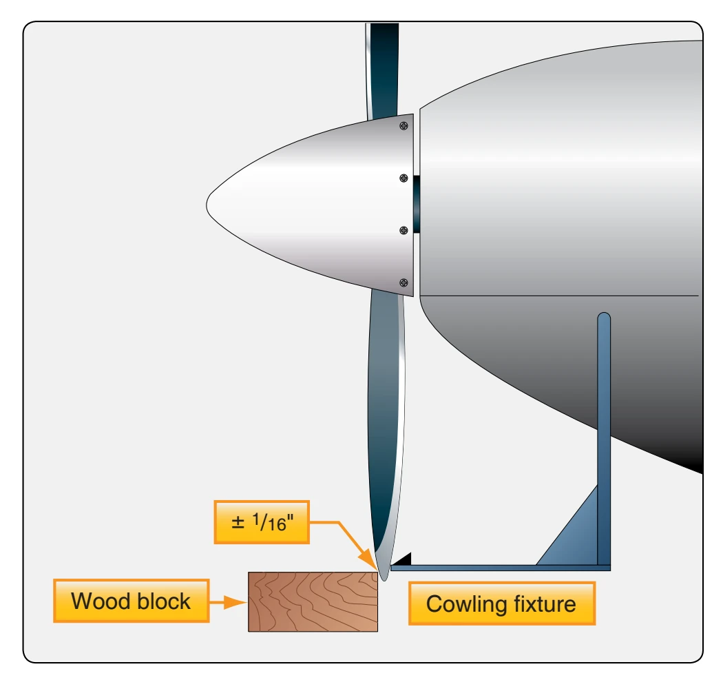
(plus or minus) from the opposite blade’s track.
- An out-of-track propeller, may be due to one or more propeller blades being bent, a bent propeller flange, or propeller mounting bolts that are either over- or undertorqued. An out-of-track propeller causes vibration and stress to the airframe and engine and may cause premature propeller failure.