
Chapter 7
Propellers
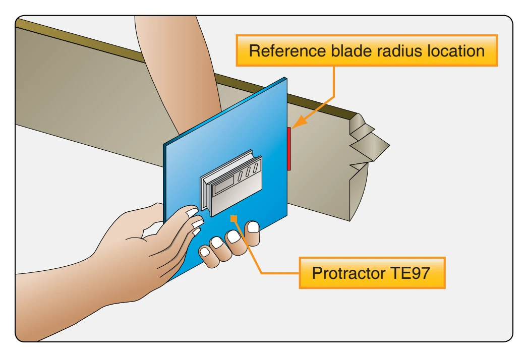
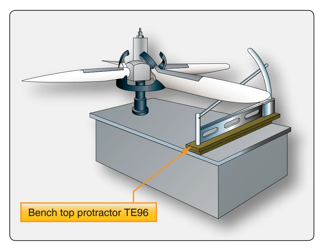
When you find an improper blade angle setting during installation or when indicated by engine performance, follow basic maintenance guidelines. From the applicable manufacturer’s instructions, obtain the blade angle setting and the station at which the blade angle is checked. Do not use metal scribes or other sharply pointed instruments to mark the location of blade stations or make reference lines on propeller blades, since such surface scratches can induce failure (stress concentrator), eventually resulting in blade failure. Use a bench-top protractor if the propeller is removed from the aircraft. [Figure 7-35] Use a handheld protractor (a digital protractor provides an easy measurement) to check blade angle if the propeller is installed on the aircraft or is placed on the knife-edge balancing stand. [Figure 7-36]
Universal Propeller Protractor
The universal propeller protractor can be used to check propeller blade angles when the propeller is on a balancing stand or installed on the aircraft engine. Figure 7-37 shows the parts and adjustments of a universal propeller protractor. The following instructions for using the protractor apply to a propeller installed on the engine. Turn the propeller until the first blade to be checked is horizontal with the leading edge up. Place the corner spirit level at right angles to the face of the protractor. Align degree and vernier scales by turning the disc adjuster before the disc is locked to the ring. The locking device is a pin that is held in the engaged position by a spring. The pin can be released by pulling it outward and turning it 90°.
Release the ring-to-frame lock (a right-hand screw with thumb nut) and turn the ring until both ring and disc zeros are at the top of the protractor.
Check the blade angle by determining how much the flat side of the block slants from the plane of rotation. First, locate a point to represent the plane of rotation by placing the protractor vertically against the end of the hub nut or any convenient surface known to lie in the plane of propeller
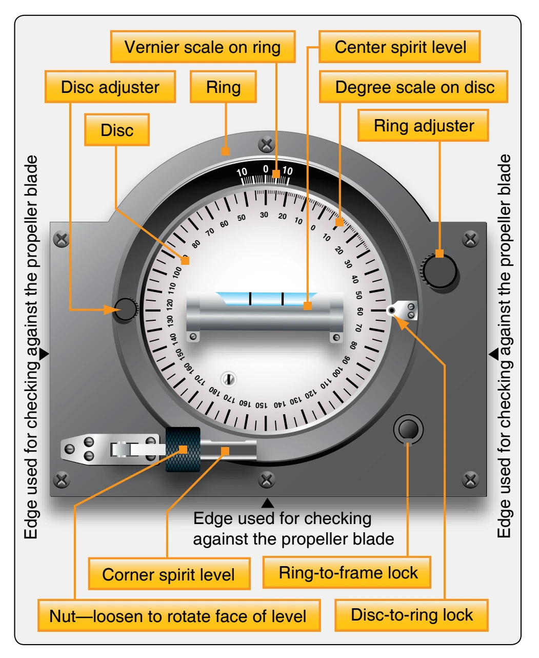
rotation. Keep the protractor vertical by the corner spirit level and turn the ring adjuster until the center spirit level is horizontal. This sets the zero of the vernier scale at a point representing the plane of propeller rotation. Then, lock the ring to the frame.
While holding the protractor by the handle with the curved edge up, release the disc-to-ring lock. Place the forward vertical edge (the edge opposite the one first used) against the blade at the station specified in the manufacturer’s instructions. Keep the protractor vertical by the corner spirit level and turn the disc adjuster until the center spirit level is horizontal. The number of degrees and tenths of a degree between the two zeros indicates the blade angle.
In determining the blade angle, remember that ten points on the vernier scale are equal to nine points on the degree scale. The graduations on the vernier scale represent tenths of a degree, but those of the degree scale represent whole degrees. The number of tenths of a degree in the blade angle is given by the number of vernier scale spaces between the zero of the vernier scale and the vernier scale graduation line nearest to perfect alignment with a degree scale graduation line. This reading should always be made on the vernier scale. The vernier scale increases in the same direction that the protractor scale increases. This is opposite to the direction of rotation of the moving element of the protractor. After making any necessary adjustment of the blade, lock it in position and repeat the same operations for the remaining blades of the propeller.
Propeller Balancing
Propeller unbalance, which is a source of vibration in an aircraft, may be either static or dynamic. Propeller static imbalance occurs when the center of gravity (CG) of the propeller does not coincide with the axis of rotation. Dynamic unbalance results when the CG of similar propeller elements, such as blades or flyweights, does not follow in the same plane of rotation. Since the length of the propeller assembly along the engine crankshaft is short in comparison to its diameter, and since the blades are secured to the hub so they lie in the same plane perpendicular to the running axis, the dynamic unbalance resulting from improper mass distribution is negligible, provided the track tolerance requirements are met. Another type of propeller unbalance, aerodynamic unbalance, results when the thrust (or pull) of the blades is unequal. This type of unbalance can be largely eliminated by checking blade contour and blade angle setting.
Static Balancing
The knife-edge test stand has two hardened steel edges mounted to allow the free rotation of an assembled propeller between them. [Figure 7-38] The knife-edge test stand must be located in a room or area that is free from any air motion, and preferably removed from any source of heavy vibration.
The standard method of checking propeller assembly balance involves the following sequence of operations:
- Insert a bushing in the engine shaft hole of the propeller.
- Insert a mandrel or arbor through the bushing.
- Place the propeller assembly so that the ends of the arbor are supported upon the balance stand knifeedges. The propeller must be free to rotate.
If the propeller is properly balanced statically, it remains at any position in which it is placed. Check two-bladed propeller assemblies for balance: first with the blades in a vertical position and then with the blades in a horizontal position. Repeat the vertical position check with the blade positions reversed; that is, with the blade that was checked in the downward position placed in the upward position.
Check a three-bladed propeller assembly with each blade placed in a downward vertical position. [Figure 7-39]
During a propeller static balance check, all blades must be at the same blade angle. Before conducting the balance check, inspect to see that each blade has been set at the same blade angle.