
Chapter 7
Propellers
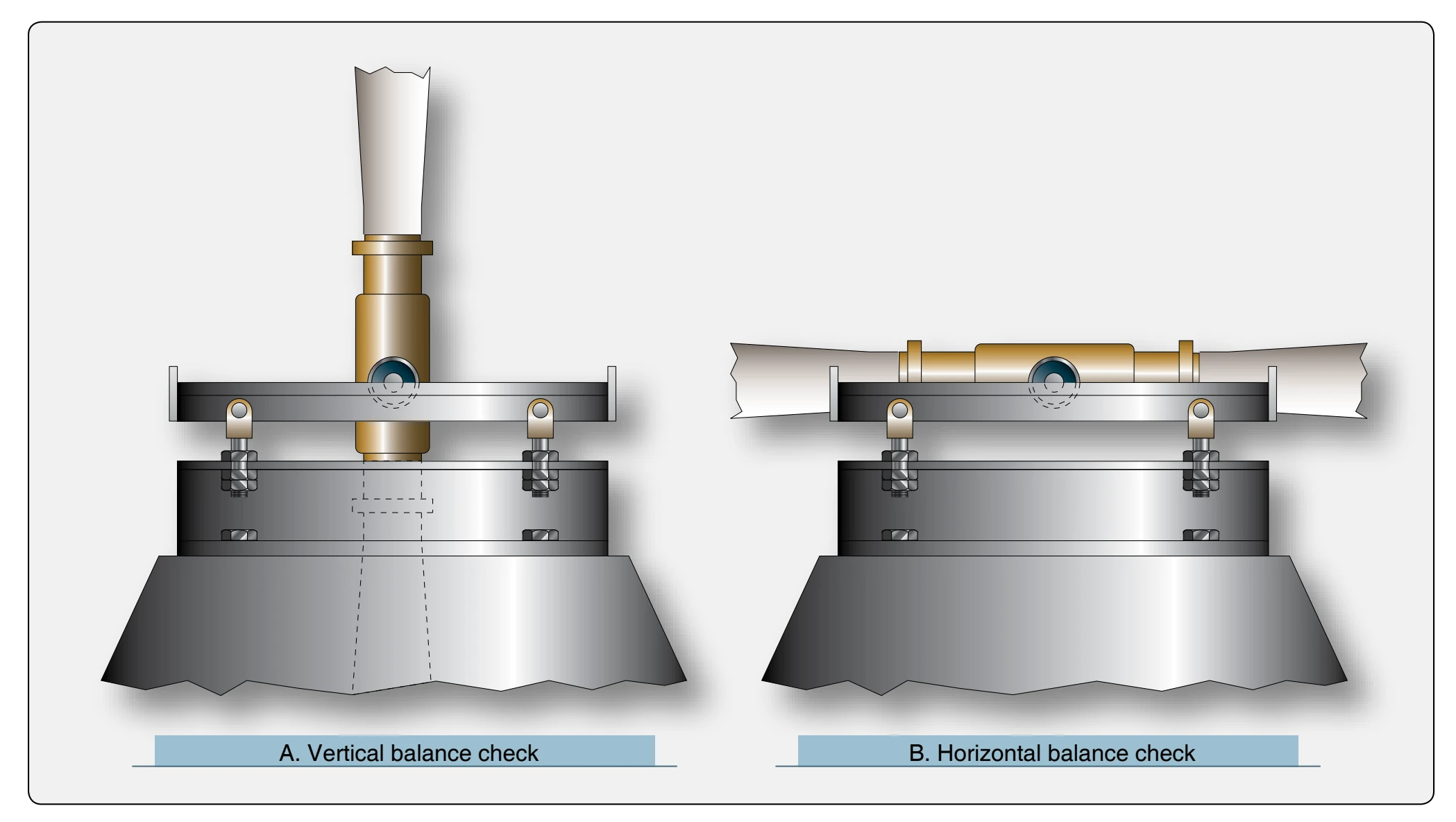
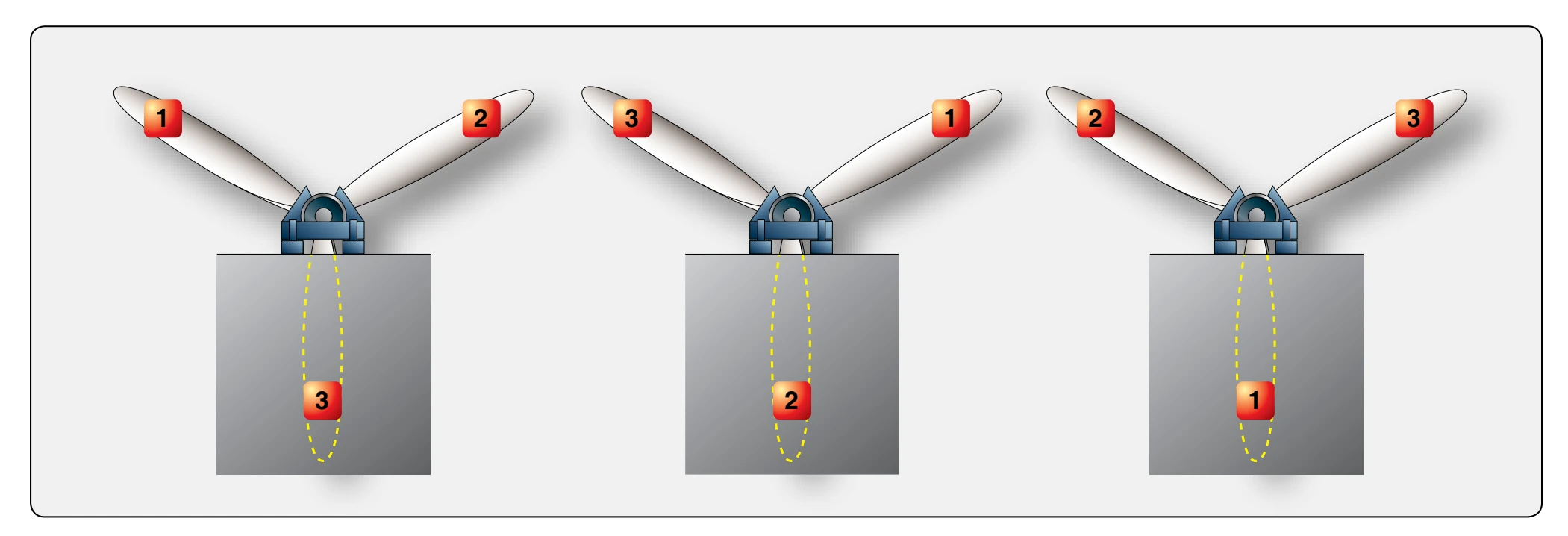
Unless otherwise specified by the manufacturer, an acceptable balance check requires that the propeller assembly have no tendency to rotate in any of the positions previously described. If the propeller balances perfectly in all described positions, it should also balance perfectly in all intermediate positions. When necessary, check for balance in intermediate positions to verify the check in the originally described positions. [Figure 7-40]
When a propeller assembly is checked for static balance and there is a definite tendency of the assembly to rotate, certain corrections to remove the unbalance are allowed.
- The addition of permanent fixed weights at acceptable locations when the total weight of the propeller assembly or parts is under the allowable limit.
- The removal of weight at acceptable locations when the total weight of the propeller assembly or parts is equal to the allowable limit.
The location for removal or addition of weight for propeller unbalance correction has been determined by the propeller manufacturer. The method and point of application of unbalance corrections must be checked to see that they are according to applicable drawings.
Dynamic Balancing
Propellers can also be dynamically balanced (spin balanced) with an analyzer kit to reduce the vibration levels of the propeller and spinner assembly. Some aircraft have the system hardwired in the aircraft and on other aircraft the sensors and cables need to be installed before the balancing run. Balancing the propulsion assembly can provide substantial reductions in transmitted vibration and noise to the cabin and also reduces excessive damage to other aircraft and engine components. The dynamic imbalance could be caused by mass imbalance or any aerodynamic imbalance. Dynamic balancing only improves the vibration caused by mass unbalance of the externally rotating components of the propulsion system. Balancing does not reduce the vibration level if the engine or aircraft is in poor mechanical condition.
Defective, worn, or loose parts will make balancing impossible. Several manufacturers make dynamic propeller balancing equipment, and their equipment operation could differ. The typical dynamic balancing system consists of a vibration sensor that is attached to the engine close to the propeller, and an analyzer unit that calculates the weight and location of balancing weights.
Balancing Procedure
Face the aircraft directly into the wind (maximum 20 knots) and place chocks at the wheels. When you have installed the analyzing equipment, run the engine up at low cruise rpm; the
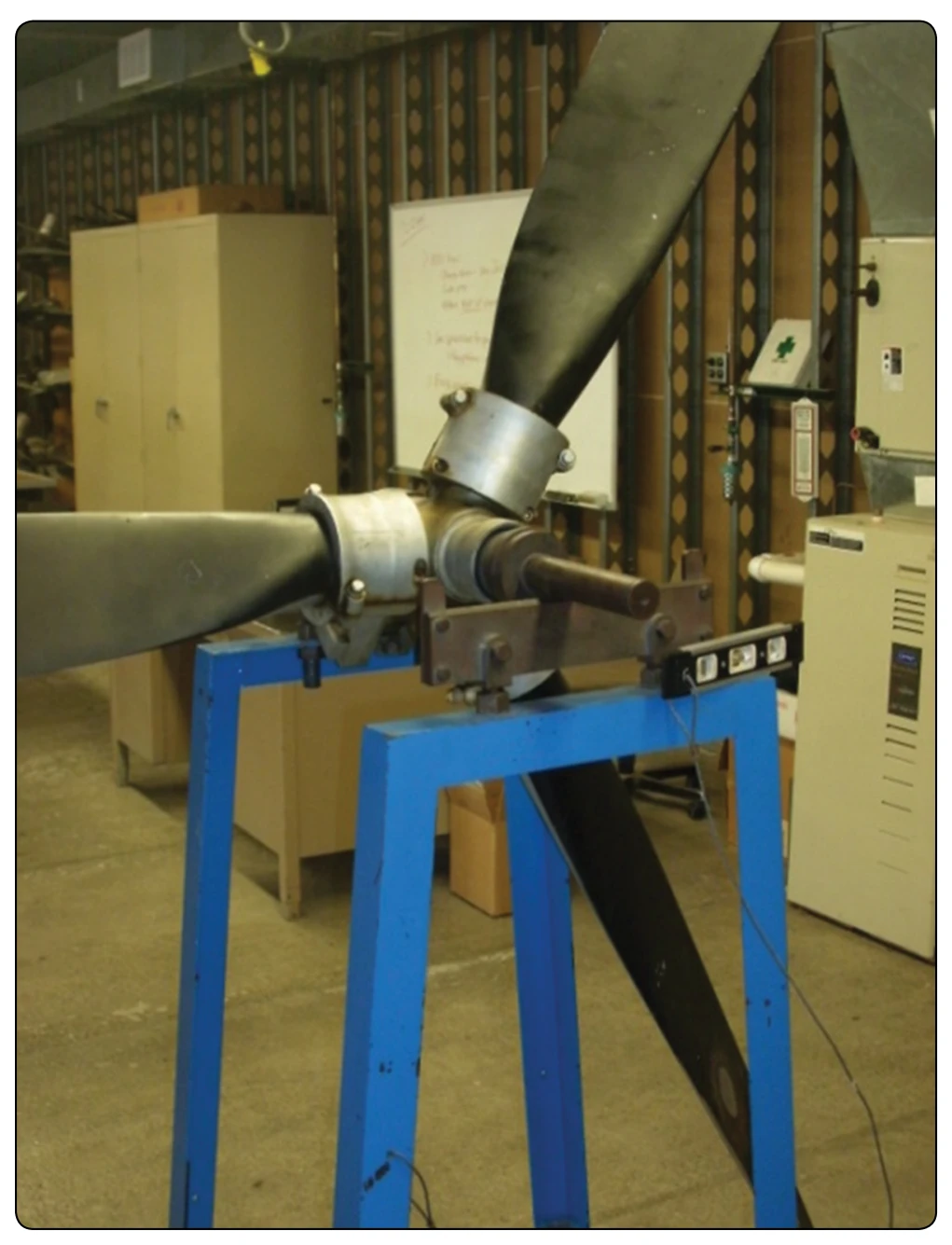
dynamic analyzer calculates the balancing weight required at each blade position. After installing the balancing weights, run the engine up again to check if the vibration levels have diminished. This process may have to be repeated several times before satisfactory results are achieved.
A dynamic balancing example procedure is listed here, but always refer to the aircraft and propeller manuals when performing any balancing procedure. Dynamic balance is accomplished by using an accurate means of measuring the amount and location of the dynamic imbalance. The number of balance weights installed must not exceed the limits specified by the propeller manufacturer. Follow the dynamic balance equipment manufacturer’s instructions for dynamic balance in addition to the specifications of the propeller.
Most equipment use an optical pickup that senses reflective tape for rpm reading. Also, there is an accelerometer mounted to the engine that senses vibration in inches per second (ips).
Visually inspect the propeller assembly before dynamic balancing. The first runup of a new or overhauled propeller assembly may leave a small amount of grease on the blades and inner surface of the spinner dome. Use Stoddard solvent (or equivalent) to completely remove any grease on the blades or inner surface of the spinner dome. Visually examine each propeller blade assembly for evidence of grease leakage. Visually examine the inner surface of the spinner dome for evidence of grease leakage. If there is no evidence of grease leakage, lubricate the propeller in accordance with the maintenance manual. If grease leakage is evident, determine the location of the leak and correct before relubricating the propeller and dynamic balancing. Before dynamic balance, record the number and location of all balance weights. Static balance is accomplished at a propeller overhaul facility when an overhaul or major repair is performed. Twelve equally spaced locations are recommended for weight attachment. Install the balancing weights using aircraft quality 10-32 or AN-3 type screws or bolts. Balance weight screws attached to the spinner bulkhead must protrude through the self-locking nuts or nut plates a minimum of one thread and a maximum of four threads. Unless otherwise specified by the engine or airframe manufacturer, Hartzell recommends that the propeller be dynamically balanced to a reading of 0.2 ips, or less. If reflective tape is used for dynamic balancing, remove the tape immediately after balancing is completed. Make a record in the propeller logbook of the number and location of dynamic balance weights, and static balance weights if they have been reconfigured.
Propeller Removal & Installation
Removal
The following procedure is for demonstration purposes only. Always use the current manufacturer’s information when removing and installing any propeller.
- Remove the spinner dome in accordance with the spinner removal procedures. Cut and remove the safety wire (if installed) on the propeller mounting studs.
- Support the propeller assembly with a sling. If the propeller is reinstalled and has been dynamically balanced, make an identifying mark (with a felt-tipped pen only) on the propeller hub and a matching mark on the engine flange to make sure of proper orientation during reinstallation to prevent dynamic imbalance.
- Unscrew the four mounting bolts from the engine bushings. Unscrew the two mounting nuts and the attached studs from the engine bushings. If the propeller is removed between overhaul intervals, mounting studs, nuts, and washers may be reused if they are not damaged or corroded.