
Chapter 8
Engine Removal & Replacement
The engine mounts are usually secured to the aircraft by special heat-treated steel bolts. The importance of using only these special bolts can be readily appreciated, since they alone support the entire weight of, and withstand all, the stresses imposed by the engine and propeller in flight. The upper bolts support the weight of the engine while the aircraft is on the ground, but when the aircraft is airborne another stress is added. This stress is torsional and affects all bolts, not just the top bolts. A typical engine mount ring shown in Figure 8-16 discloses fittings and attachment points located at four positions on the engine mount structure. Each fitting houses a dynamic engine mount.
The section of an engine mount where the engine is attached is known as the engine mount ring. It is usually constructed of steel tubing having a larger diameter than the rest of the mount structure. It is circular in shape so that it can surround the engine, which is near the point of balance for the engine. The engine is usually attached to the mount by dynafocal mounts, attached to the engine at the point of balance forward of the mount ring. Other types of mounting devices are also used to secure the different engines to their mount rings.
As aircraft engines became larger and produced more power, some method was needed to absorb their vibration. This demand led to the development of the rubber and steel enginesuspension units called shock mounts. This combination permits restricted engine movement in all directions. These vibration isolators are commonly known as flexible, or elastic, shock mounts. An interesting feature common to most shock mounts is that the rubber and metal parts are arranged so that, under normal conditions, rubber alone supports the engine. Of course, if the engine is subjected to abnormal shocks or loads, the metal snubbers limit excessive movement of the engine. Dynafocal engine mounts, or vibration isolators, are units that give directional support to the engines. Dynafocal engine mounts have the mounting pad angled to point to the CG of the engines mass. [Figure 8-16]
Mounts for Turbofan Engines
The engine mounts on most turbofan engines perform the same basic functions of supporting the engine and transmitting the loads imposed by the engine to the aircraft structure. Most turbine engine mounts are made of stainless steel and are typically located as illustrated in Figure 8-17. Some engine mounting systems use two mounts to support the forward end of the engine and a single mount at the rear end.
Turbine Vibration Isolation Engine Mounts
The vibration isolator engine mounts support the power plants and isolate the airplane structure from adverse engine vibrations. Each power plant is generally supported by forward vibration isolator mounts and an aft vibration isolator mount.
The forward vibration isolator engine mounts carry vertical, side, and axial (thrust) loads and allow engine growth due to thermal expansion. The aft mounts take only vertical and side loads; however, they will also accommodate thermal expansion of the engine without applying axial loads to the engine flanges.
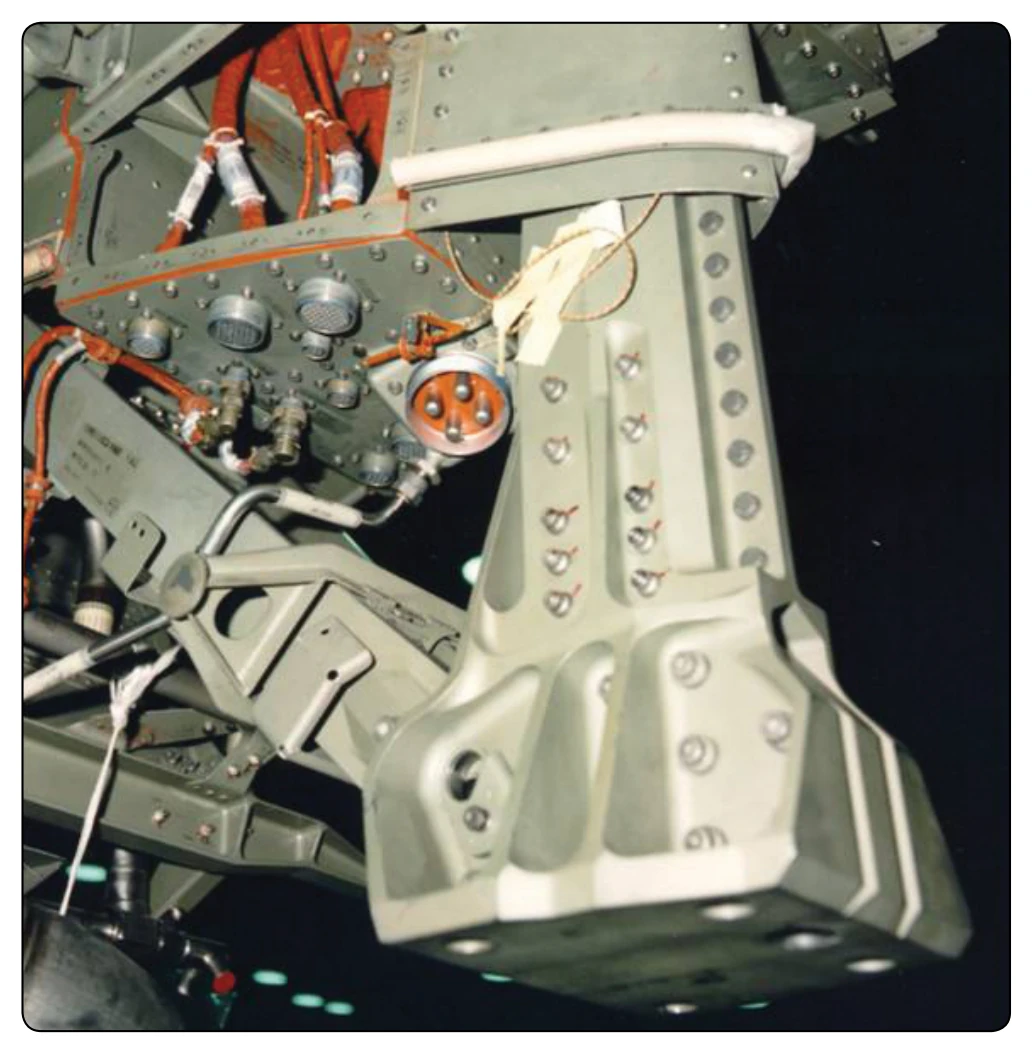
The vibration isolators consist of a resilient material permanently enclosed in a metal case. As an engine vibrates, the resilient material deforms slightly, thereby dampening the vibrations before they reach the airplane structure. If complete failure or loss of the resilient material occurs, the isolators will continue to support the engine.
Preservation & Storage of Engines
An engine awaiting overhaul or return to service after overhaul must be given careful attention. It does not receive the daily care and attention necessary to detect and correct early stages of corrosion. For this reason, some definite action must be taken to prevent corrosion from affecting the engine. Engines that are not flown regularly may not achieve normal service life because of corrosion in and around the cylinders. The normal combustion process creates moisture and corrosive by-products that attack the unprotected surfaces of the cylinder walls, valves, and any other exposed areas that are unprotected. In engines that have accumulated 50 hours or more time in service in a short period, the cylinder walls have acquired a varnish that tends to protect them from corrosive action; engines under favorable atmospheric conditions can remain inactive for several weeks without evidence of damage by corrosion. This is the best-case scenario, but aircraft that operate close to oceans, lakes, rivers, and humid regions have a greater need for engine preservation than engines operated in dry low humid areas.
Corrosion-Preventive Materials
An engine in service is in a sense self-purging of moisture, since the heat of combustion evaporates the moisture in and around the engine, and the lubricating oil circulated through the engine temporarily forms a protective coating on the metal it contacts. If the operation of an engine in service is limited or suspended for a period of time, the engine is preserved to a varying extent, depending upon how long it is to be inoperative. There are three types of engine storage: active engine, temporary, and indefinite. An engine in active storage is defined as having at least one continuous hour of operation with an oil temperature of at least 165 °F to 200 °F and storage time not to exceed 30 days. Temporary storage describes an aircraft and engine that is not flown for 30 to 90 days, and indefinite storage is for an aircraft not to be flown for over 90 days or is removed from the aircraft for extended time.
Corrosion-Preventive Compounds
The preservation materials discussed are used for all types of engine storage. Corrosion-preventive compounds are petroleum-based products that form a wax-like film over the metal to which they are applied. Several types of corrosionpreventive compounds are manufactured according to different specifications to fit the various aviation needs. The type mixed with engine oil to form a corrosion-preventive mixture is a relatively light compound that readily blends with engine oil when the mixture is heated to the proper temperature.
The light mixture is available in three forms: MIL-C-6529C type I, type II, or type III. Type I is a concentrate and must be blended with three parts of MIL-L-22851 or MIL-L-6082C (SAE J1966) grade 1100 oil to one part of concentrate. Type II is a ready-mixed material with MIL-L-22851 or grade 1100 oil and does not require dilution. Type III is a ready-mixed material with grade 1010 oil for use in turbine engines only. The light mixture is intended for use when a preserved engine is to remain inactive for less than 30 days. It is also used to spray cylinders and other designated areas.
The desired proportions of lubricating oil, and either heavy or light corrosion-preventive compound, must not be obtained by adding the compound to the oil already in the engine. The mixture must be prepared separately before applying to the engine or placing in an oil tank.
A heavy compound is used for the dip treating of metal parts and surfaces. It must be heated to a high temperature to be sufficiently liquid to effectively coat the objects to be preserved. A commercial solvent, or kerosene spray, is used to remove corrosion-preventive compounds from the engine or parts when they are being prepared for return to service.
Although corrosion-preventive compounds act as an insulator from moisture, in the presence of excessive moisture, they eventually break down and corrosion begins. Also, the compounds eventually dry because their oil base gradually evaporates. This allows moisture to contact the engine’s metal and aids in corroding it. Therefore, when an engine is stored in a shipping case or container, some dehydrating (moisture removing) agent must be used to remove the moisture from the air in and around the engine.