Chapter 8
Engine Removal & Replacement
Open the engine side panels and remove the nacelle access panels. Disconnect the engine thermocouple leads at the terminal board. Before disconnecting any lines, make sure that all fuel, oil, and hydraulic fluid valves are closed. Plug all lines as they are disconnected to prevent entrance of foreign material.
Remove the clamps securing the bleed-air ducts at the firewall. Then, disconnect the electrical connector plugs, engine breather and vent lines, and fuel, oil, and hydraulic lines.
Disconnect the engine power lever and propeller control rods or cables. Remove the covers from the QECA lift points, attach the QECA sling, and remove slack from the cables using a suitable hoist. The sling must be adjusted to position the hoisting eye over the QECA CG. Failure to do so may result in engine damage.
Remove the engine mount bolts. The QECA is then ready to be removed. Recheck all of the disconnect points to make certain they are all disconnected prior to moving the engine. Move the engine forward, out of the nacelle structure, until it clears the aircraft. Lower the QECA into position on the QECA stand and secure it prior to removing the engine sling.
The installation procedures are essentially the reverse of the removal procedures. Move the QECA straight back into the nacelle structure and align the mount bolt holes and the firewall. Start all the bolts before torqueing. With all the bolts started, and using the correct torque wrench adapter, tighten the mount bolts to their proper torque. Remove the sling and install the access covers at the lift point. Using the reverse of the removal procedures, connect the various lines and connectors. New O-ring seals should be used. The manufacturer’s instructions should be consulted for the proper torque limits for the various clamps and bolts.
After installation, an engine runup should be made. In general, the runup consists of checking proper operation of the powerplant and related systems. Several functional tests are performed to evaluate each phase of engine operation. The tests and procedures outlined by the engine or airframe manufacturers should be followed.
Reciprocating Helicopter Engine & QECA
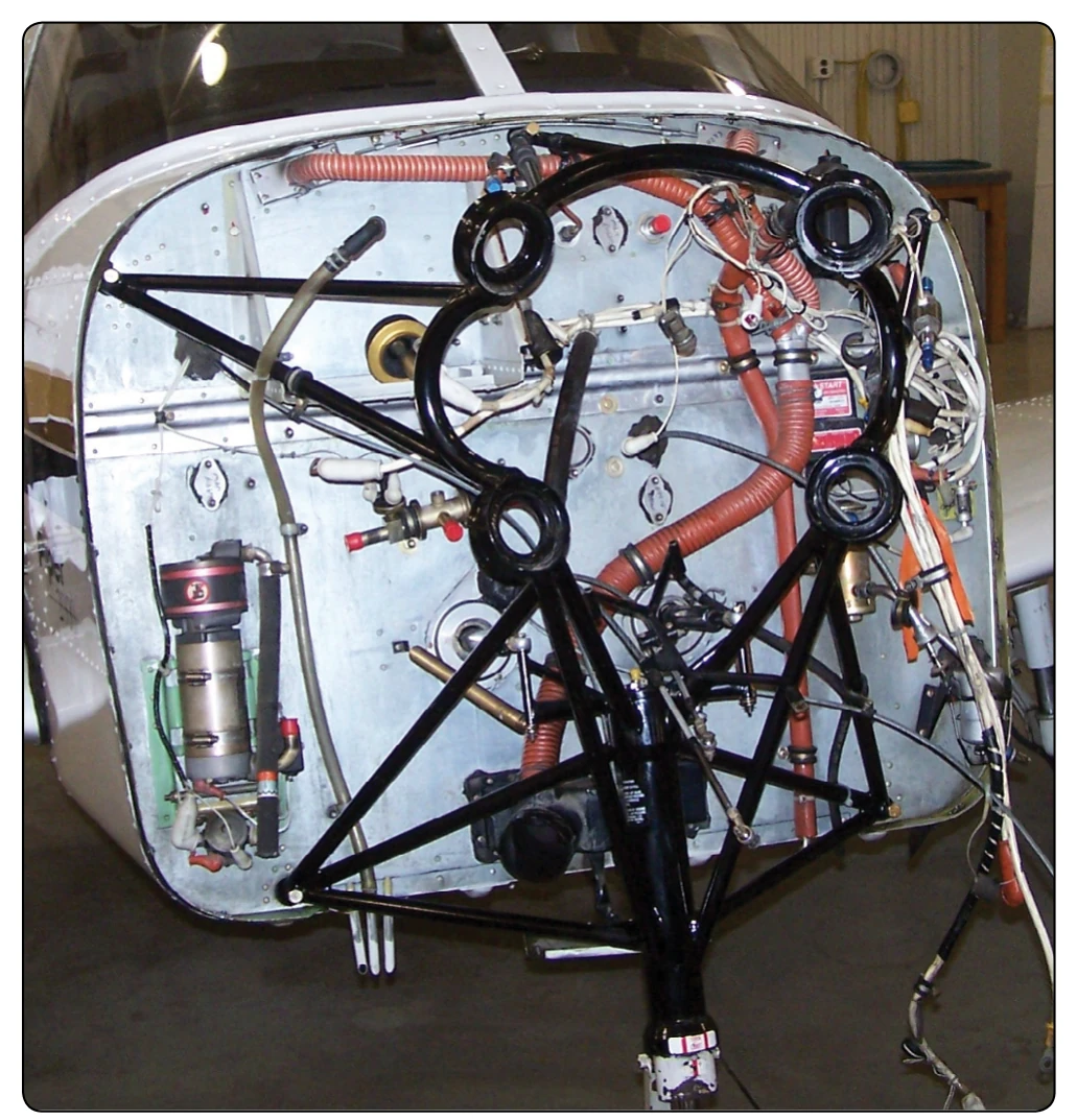
The engine is installed facing aft with the propeller shaft approximately 39° above horizontal. The engine is supported by the engine mount, which is bolted to the fuselage structure. The installation of the engine provides for ease of maintenance by allowing easy access to all accessories and components when the engine access doors are opened. The QECA contains the engine, engine mount, engine accessories, engine controls, fuel system, lubrication system, ignition system, cooling system, and hydromechanical clutch and fan assembly.
Removal of Helicopter QECA
Prior to removing the helicopter QECA, the engine should be preserved if it is possible to do so. Then, shut off the fuel supply to the engine and drain the oil. Make the disconnections necessary to remove the QECA, and then perform the following steps:
- Attach the engine lifting sling to a hoist of at least a two-ton capacity.
- Raise the hoist to apply a slight lift to the QECA. Loosen both engine mount lower attachment bolt nuts before leaving the upper attachment bolts.
- Remove the bolts from the sway braces and remove both engine upper attachment bolts. Then, remove both engine mount lower attachment bolts and remove the QECA from the helicopter. Mount the power package in a suitable workstand and remove the sling.
Installation, Rigging, & Adjustment of Helicopter QECA
The installation of a new or an overhauled engine is in reverse of the removal procedure. The manufacturer’s instructions for the helicopter must be consulted to ascertain the correct interchange of parts from the old engine to the new engine. The applicable maintenance instructions should be followed. Refer to the Maintenance Instructions Manual and associated technical publications for detailed information concerning rigging the throttle, mixture control, cable tensions, and related data.
Testing the Engine Installation
Normal engine run-in procedures must be followed in accordance with the manufacturer’s instructions. A flight test is usually performed after the engine has been installed and the engine controls have been adjusted.
Engine Mounts
Mounts for Reciprocating Engines
Most aircraft equipped with reciprocating engines use an engine mount structure made of welded steel tubing. The mount is constructed in one or more sections that incorporate the engine mount ring, bracing members (V-struts), and fittings for attaching the mount to the wing nacelle.