
Chapter 2
Aerodynamics of Flight
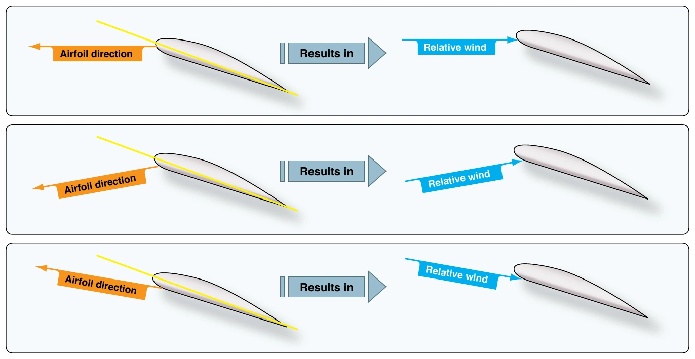
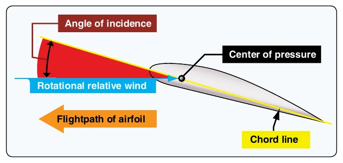
Knowledge of relative wind is essential for an understanding of aerodynamics and its practical flight application for the pilot. Relative wind is airflow relative to an airfoil. Movement of an airfoil through the air creates relative wind. Relative wind moves in a direction parallel to but opposite of the movement of the airfoil. [Figure 2-15]
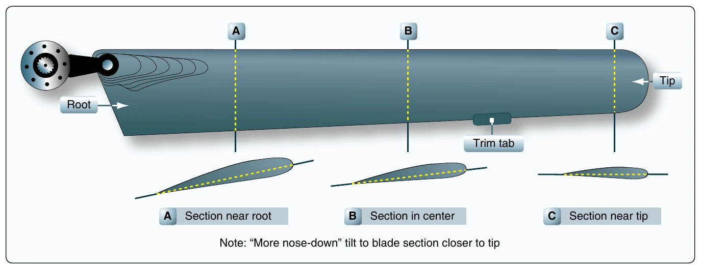
There are two parts to wind passing a rotor blade:
- Horizontal part—caused by the blades turning plus movement of the helicopter through the air [Figure 2-16]
- Vertical part—caused by the air being forced down through the rotor blades plus any movement of the air relative to the blades caused by the helicopter climbing or descending [Figures 2-17 and 2-18]
Rotational Relative Wind (Tip-Path Plane)
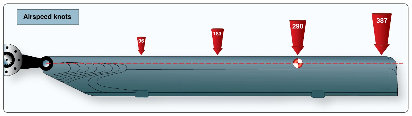
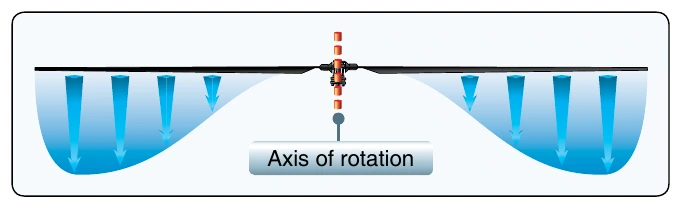
The rotation of rotor blades as they turn about the mast produces rotational relative wind (tip-path plane). The term rotational refers to the method of producing relative wind. Rotational relative wind flows opposite the physical flightpath of the airfoil, striking the blade at 90° to the leading edge and parallel to the plane of rotation; and it is constantly changing in direction during rotation. Rotational relative wind velocity is highest at blade tips, decreasing uniformly to zero at the axis of rotation (center of the mast). [Figure 2-19]
Resultant Relative Wind
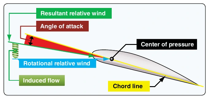
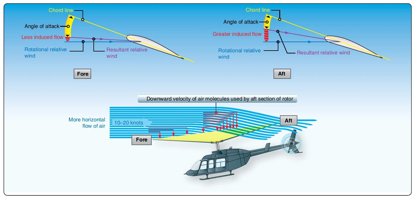
The resultant relative wind at a hover is rotational relative wind modified by induced flow. This is inclined downward at some angle and opposite the effective flightpath of the airfoil, rather than the physical flightpath (rotational relative wind). The resultant relative wind also serves as the reference plane for development of lift, drag, and total aerodynamic force (TAF) vectors on the airfoil. [Figure 2-20] When the helicopter has horizontal motion, airspeed further modifies the resultant relative wind. The airspeed component of relative wind results from the helicopter moving through the air. This airspeed component is added to, or subtracted from, the rotational relative wind depending on whether the blade is advancing or retreating in relation to helicopter movement. Introduction of airspeed relative wind also modifies induced flow. Generally, the downward velocity of induced flow is reduced. The pattern of air circulation through the disk changes when the aircraft has horizontal motion. As the helicopter gains airspeed, the addition of forward velocity results in decreased induced flow velocity. This change results in an improved efficiency (additional lift) being produced from a given blade pitch setting.
Induced Flow (Downwash)
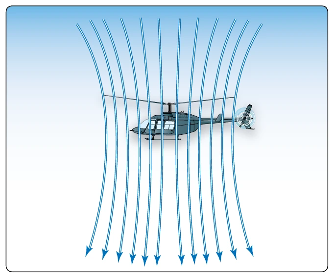
At flat pitch, air leaves the trailing edge of the rotor blade in the same direction it moved across the leading edge; no lift or induced flow is being produced. As blade pitch angle is increased, the rotor disk induces a downward flow of air through the rotor blades creating a downward component of air that is added to the rotational relative wind. Because the blades are moving horizontally, some of the air is displaced downward. The blades travel along the same path and pass a given point in rapid succession. Rotor blade action changes the still air to a column of descending air. Therefore, each blade has a decreased AOA due to the downwash. This downward flow of air is called induced flow (downwash). It is most pronounced at a hover under no-wind conditions. [Figure 2-21]
In Ground Effect (IGE)
Ground effect is the increased efficiency of the rotor disk caused by interference of the airflow when near the ground. The air pressure or density is increased, which acts to decrease the downward velocity of air. Ground effect permits relative wind to be more horizontal, lift vector to be more vertical, and induced drag to be reduced. These conditions allow the rotor disk to be more efficient. Maximum ground effect is achieved when hovering over smooth hard surfaces. When hovering over surfaces as tall grass, trees, bushes, rough terrain, and water, maximum ground effect is reduced. Rotor efficiency is increased by ground effect to a height of about one rotor diameter (measured from the ground to the rotor disk) for most helicopters. Since the induced flow velocities are decreased, the AOA is increased, which requires a reduced blade pitch angle and a reduction in induced drag. This reduces the power required to hover IGE. [Figure 2-22]