
Chapter 5
Flight Instruments
The flux gate compass that drives slaved gyros uses the characteristic of current induction. The flux valve is a small, segmented ring, like the one in Figure 5-23, made of soft iron that readily accepts lines of magnetic flux. An electrical coil is wound around each of the three legs to accept the current induced in this ring by the Earth’s magnetic field. A coil wound around the iron spacer in the center of the frame has 400-Hz alternating current (A.C.) flowing through it. During the times when this current reaches its peak, twice during each cycle, there is so much magnetism produced by this coil that the frame cannot accept the lines of flux from the Earth’s field.
But as the current reverses between the peaks, it demagnetizes the frame so it can accept the flux from the Earth’s field. As this flux cuts across the windings in the three coils, it causes current to flow in them. These three coils are connected in such a way that the current flowing in them changes as the heading of the aircraft changes. [Figure 5-24]
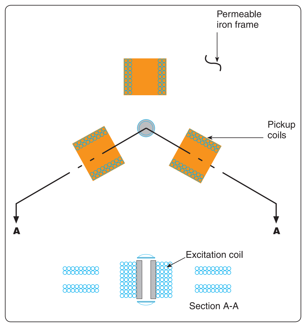
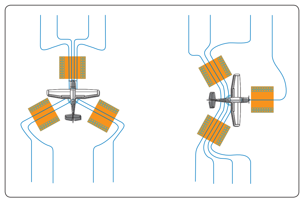
The three coils are connected to three similar but smaller coils in a synchro inside the instrument case. The synchro rotates the dial of a radio magnetic indicator (RMI) or a horizontal situation indicator (HSI).
Remote Indicating Compass
Remote indicating compasses were developed to compensate for the errors and limitations of the older type of heading indicators. The two panel-mounted components of a typical system are the pictorial navigation indicator and the slaving control and compensator unit. [Figure 5-25] The pictorial navigation indicator is commonly referred to as an HSI.
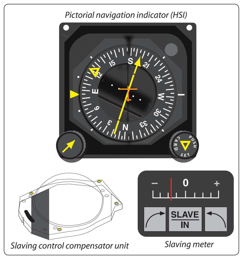
The slaving control and compensator unit has a pushbutton that provides a means of selecting either the “slaved gyro” or “free gyro” mode. This unit also has a slaving meter and two manual heading-drive buttons. The slaving meter indicates the difference between the displayed heading and the magnetic heading. A right deflection indicates a clockwise error of the compass card; a left deflection indicates a counterclockwise error. Whenever the aircraft is in a turn and the card rotates, the slaving meter shows a full deflection to one side or the other. When the system is in “free gyro” mode, the compass card may be adjusted by depressing the appropriate heading-drive button.
A separate unit, the magnetic slaving transmitter is mounted remotely; usually in a wingtip to eliminate the possibility of magnetic interference. It contains the flux valve, which is the direction-sensing device of the system. A concentration of lines of magnetic force, after being amplified, becomes a signal relayed to the heading indicator unit, which is also remotely mounted. This signal operates a torque motor in the heading indicator unit that processes the gyro unit until it is aligned with the transmitter signal. The magnetic slaving transmitter is connected electrically to the HSI.
There are a number of designs of the remote indicating compass; therefore, only the basic features of the system are covered here. Instrument pilots must become familiar with the characteristics of the equipment in their aircraft.
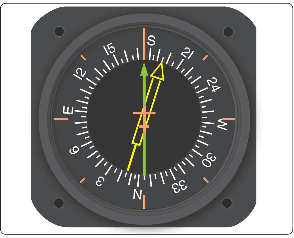
As instrument panels become more crowded and the pilot’s available scan time is reduced by a heavier flight deck workload, instrument manufacturers have worked toward combining instruments. One good example of this is the RMI in Figure 5-26. The compass card is driven by signals from the flux valve, and the two pointers are driven by an automatic direction finder (ADF) and a very high frequency omnidirectional range (VOR).
Gyroscopic Systems
Flight without reference to a visible horizon can be safely accomplished by the use of gyroscopic instrument systems and the two characteristics of gyroscopes, which are rigidity and precession. These systems include attitude, heading, and rate instruments, along with their power sources. These instruments include a gyroscope (or gyro) that is a small wheel with its weight concentrated around its periphery. When this wheel is spun at high speed, it becomes rigid and resists tilting or turning in any direction other than around its spin axis.
Attitude and heading instruments operate on the principle of rigidity. For these instruments, the gyro remains rigid in its case and the aircraft rotates about it. Rate indicators, such as turn indicators and turn coordinators, operate on the principle of precession. In this case, the gyro precesses (or rolls over) proportionate to the rate the aircraft rotates about one or more of its axes.
Power Sources
Aircraft and instrument manufacturers have designed redundancy in the flight instruments so that any single failure does not deprive the pilot of the ability to safely conclude the flight. Gyroscopic instruments are crucial for instrument flight; therefore, they are powered by separate electrical or pneumatic sources.
Pneumatic Systems
Pneumatic gyros are driven by a jet of air impinging on buckets cut into the periphery of the wheel. On many aircraft this stream of air is obtained by evacuating the instrument case with a vacuum source and allowing filtered air to flow into the case through a nozzle to spin the wheel.