
Chapter 5
Flight Instruments
The compass housing is entirely full of compass fluid. To prevent damage or leakage when the fluid expands and contracts with temperature changes, the rear of the compass case is sealed with a flexible diaphragm, or with a metal bellows in some compasses.
Magnetic Compass Theory of Operations
The magnets align with the Earth’s magnetic field and the pilot reads the direction on the scale opposite the lubber line.
Magnetic fields caused by aircraft electronics and wiring can effect the accuracy of the magnetic compass. This induced error is called compass deviation. Compensator assemblies mounted on the compass allow aviation maintenance technicians (AMTs) to calibrate the compass by creating magnetic fields inside of the compass housing. The compensator assembly has two shafts whose ends have screwdriver slots accessible from the front of the compass. Each shaft rotates one or two small compensating magnets. The end of one shaft is marked E-W, and its magnets affect the compass when the aircraft is pointed east or west. The other shaft is marked N-S and its magnets affect the compass when the aircraft is pointed north or south.
Magnetic Compass Errors
The magnetic compass is the simplest instrument in the panel, but it is subject to a number of errors that must be considered.
Variation
The Earth rotates about its geographic axis; maps and charts are drawn using meridians of longitude that pass through the geographic poles. Directions measured from the geographic poles are called true directions. The north magnetic pole to which the magnetic compass points is not collocated with the geographic north pole, but is some 1,300 miles away; directions measured from the magnetic poles are called magnetic directions. In aerial navigation, the difference between true and magnetic directions is called variation. This same angular difference in surveying and land navigation is called declination.
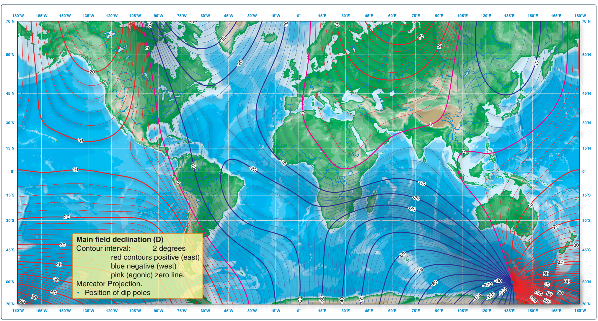
Figure 5-17 shows the isogonic lines that identify the number of degrees of variation in their area. The line that passes near Chicago is called the agonic line. Anywhere along this line the two poles are aligned, and there is no variation. East of this line, the magnetic pole is to the west of the geographic pole and a correction must be applied to a compass indication to get a true direction.
Flying in the Washington, D.C. area, for example, the variation is 10° west. If the pilot wants to fly a true course of south (180°), the variation must be added to this resulting in a magnetic course to fly of 190°. Flying in the Los Angeles, CA area, the variation is 14° east. To fly a true course of 180° there, the pilot would have to subtract the variation and fly a magnetic course of 166°. The variation error does not change with the heading of the aircraft; it is the same anywhere along the isogonic line.
Deviation
The magnets in a compass align with any magnetic field. Local magnetic fields in an aircraft caused by electrical current flowing in the structure, in nearby wiring or any magnetized part of the structure, conflict with the Earth’s magnetic field and cause a compass error called deviation.
Deviation, unlike variation, is different on each heading, but it is not affected by the geographic location. Variation error cannot be reduced or changed, but deviation error can be minimized when a pilot or AMT performs the maintenance task known as “swinging the compass.”
Some airports have a compass rose, which is a series of lines marked out on a taxiway or ramp at some location where there is no magnetic interference. Lines, oriented to magnetic north, are painted every 30°, as shown in Figure 5-18.
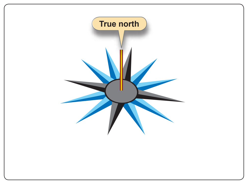
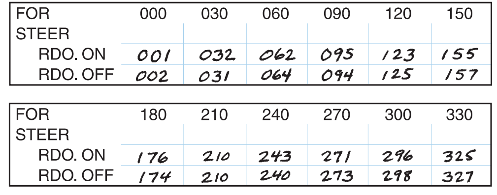
The pilot or AMT aligns the aircraft on each magnetic heading and adjusts the compensating magnets to minimize the difference between the compass indication and the actual magnetic heading of the aircraft. Any error that cannot be removed is recorded on a compass correction card, like the one in Figure 5-19, and placed in a cardholder near the compass. If the pilot wants to fly a magnetic heading of 120° and the aircraft is operating with the radios on, the pilot should fly a compass heading of 123°.
The corrections for variation and deviation must be applied in the correct sequence as shown below starting from the true course desired.