Chapter 1
Departure Procedures
All departure procedures are initially assessed for obstacle clearance based on a 40:1 Obstacle Clearance Surface (OCS). If no obstacles penetrate this 40:1 OCS, the standard 200 ft/NM climb gradient provides a minimum of 48 ft/NM of clearance above objects that do not penetrate the slope. The departure design must also include the acquisition of positive course guidance (PCG), typically within 5 to 10 NM of the DER for straight departures. Even when aircraft performance greatly exceeds the minimum climb gradient, the published departure routing must always be flown.
Airports publish the declared distances in the A/FD section of the CS. These include takeoff runway available (TORA), takeoff distance available (TODA), accelerate-stop distance available (ASDA), and landing distance available (LDA). These distances are calculated by adding to the full length of paved runway any applicable clearway or stop-way and subtracting from that sum the sections of the runway unsuitable for satisfying the required takeoff run, takeoff, accelerate/stop, or landing distance as shown in Figure 1-16.
Optimally, the 40 to 1 slope would work for every departure design; however, due to terrain and manmade obstacles, it is often necessary to use alternative requirements to accomplish a safe, obstacle-free departure design. In such cases, the design of the departure may incorporate a climb gradient greater than 200 ft/NM, an increase in the standard takeoff minimums to allow the aircraft to “see and avoid” the obstacles, a standard climb of 200 ft/NM with a specified reduced takeoff length, or a combination of these options and a specific departure route.
If a departure route is specified, it must be flown in conjunction with the other options.
The obstacle environment may require a climb gradient greater than 200 ft/NM. In these cases, the ROC provided above obstacles is equivalent to 24 percent of the published climb gradient. The required climb gradient, for obstacle purposes on ODPs and SIDs, is obtained by using the formulas:
Standard Formula DoD Option*
CG = O – E CG = (48D + O) – E 0.76 D D
O = obstacle mean sea level (MSL) elevation E = climb gradient starting MSL elevation D = distance (NM) from DER to the obstacle
Examples: 2049 – 1221 (48 × 3.1 + 2049) – 1221 = 351.44 = 315.10 0.76 × 3.1 3.1
Round to 352 ft/NM Round to 316 ft/NM *Military only
These formulas are published in FAA Order 8260.3 for calculating the required climb gradient to clear obstacles.
The following formula is used for calculating SID climb gradients for other than obstacles (i.e., ATC requirements)
CG = A – E D
A = “climb to” altitude E = climb gradient starting MSL elevation D = distance (NM) from the beginning of the climb
Example:
3000 – 1221 = 355.8 round to 356 ft/NM 5
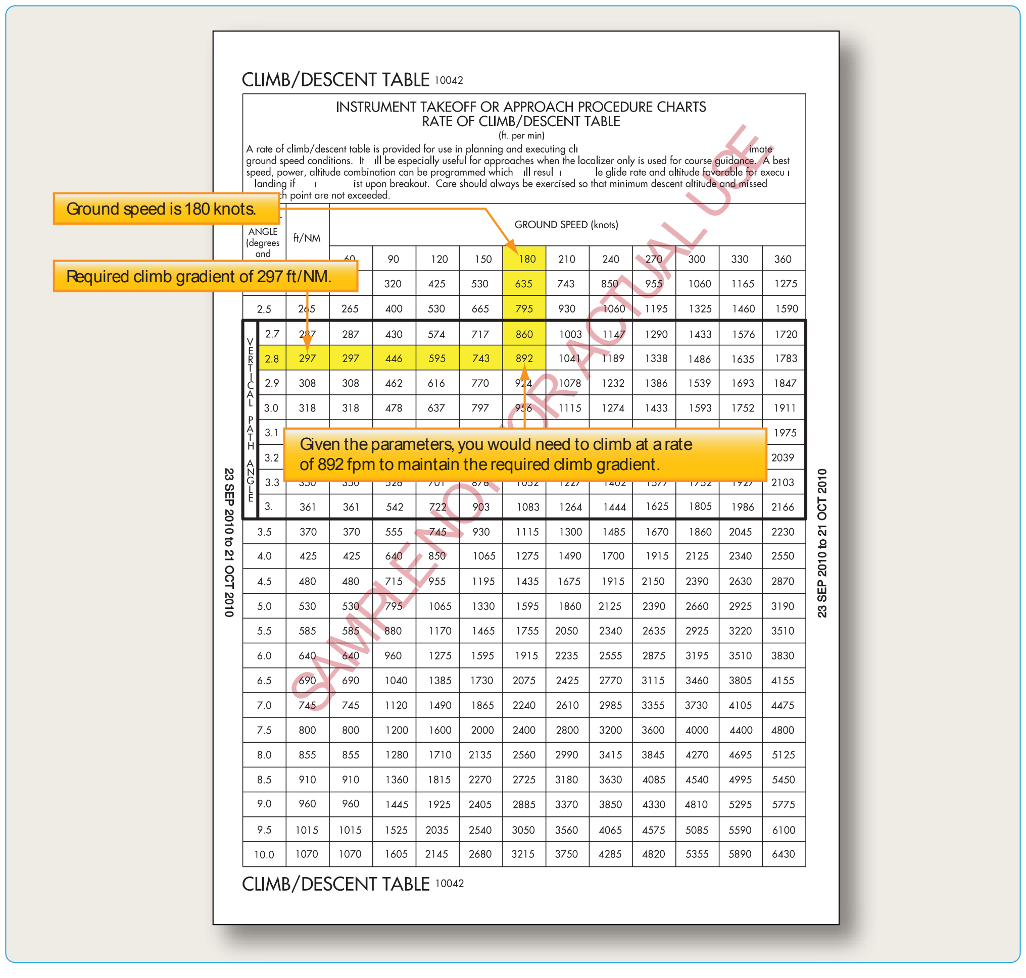
The published climb gradient, obstacle or otherwise, is treated as a plane which must not be penetrated from above until reaching the stated height or has reached the en route environment (e.g., above the MEA, MOCA). Departure design, including climb gradients, does not take into consideration the performance of the aircraft; it only considers obstacle protection for all aircraft. TERPS criteria assume the aircraft is operating with all available engines and systems fully functioning. Development of contingency procedures, required to cover the case of an engine failure, engine out procedures (EOPs) or other emergency in flight that may occur after liftoff, is the responsibility of the operator. When a climb gradient is required for a specific departure, it is vital that pilots fully understand the performance of their aircraft and determine if it can comply with the required climb. The standard climb of 200 ft/NM is not an issue for most aircraft. When an increased climb gradient is specified due to obstacle issues, it is important to calculate aircraft performance, particularly when flying out of airports at higher altitudes on warm days. To aid in the calculations, the front matter of every TPP booklet contains a rate of climb table that relates specific climb gradients and typical groundspeeds. [Figure 1-17].