Chapter 2
En Route Operations
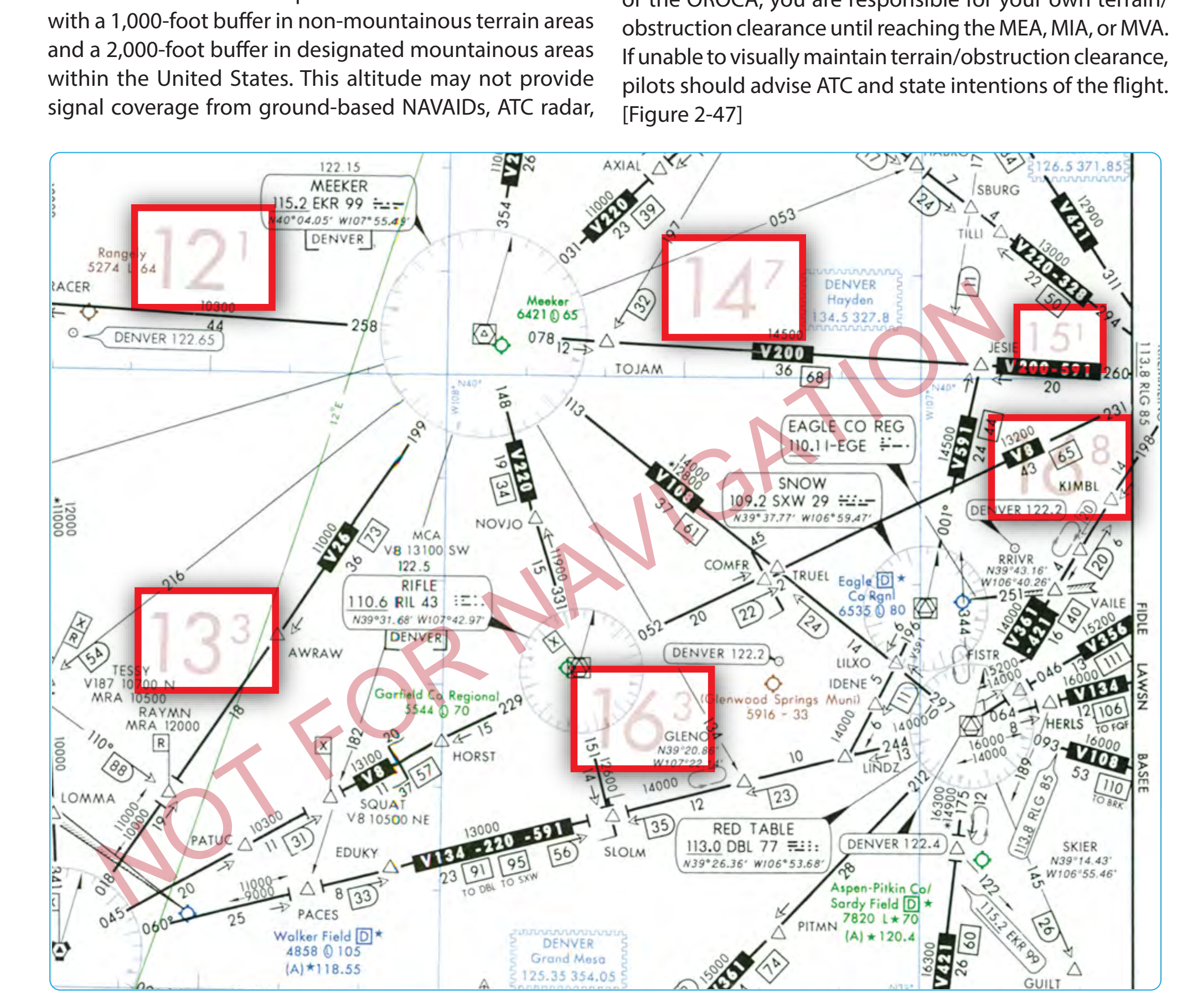
When departing an airport VFR intending to or needing to obtain an IFR clearance en route, you must be aware of the position of your aircraft relative to terrain and obstructions. When accepting a clearance below the MEA, MIA, MVA, For all random RNAV flights, there needs to be at least one waypoint in each ARTCC area through which you intend to fly. One of the biggest problems in creating an RNAV direct route is determining if the route goes through special use airspace. For most direct routes, the chances of going through prohibited, restricted, or special use airspace are good. In the United States, all direct routes should be planned to avoid prohibited or restricted airspace by at least 3 NM. If a bend in a direct route is required to avoid special use airspace, the turning point needs to be part of the flight plan. Two of the most prominent long range navigation systems today include FMS with integrated GPS and stand-alone GPS. The following example is a simplified overview showing how the RNAV systems might be used to fly a random RNAV route.
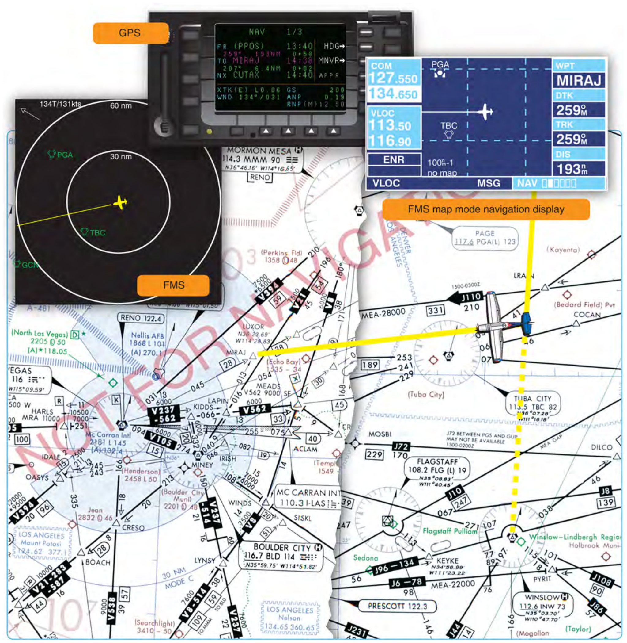
Shown in Figure 2-48, the aircraft is northeast of Tuba City VORTAC at FL 200 using RNAV (showing both GPS and FMS), RNAV direct on a southwesterly heading to Lindbergh Regional Airport in Winslow. As the pilot is monitoring his or her position and cross-checking the avionics against the high altitude en route chart, he or she receives a company message instructing to divert to Las Vegas, requiring a change in the flight plan as highlighted on the depicted chart excerpt.
During the flight deck review of the high and low altitude en route charts, the pilot determines that the best course of action is to fly direct to the MIRAJ waypoint, 28 DME northeast of the Las Vegas VORTAC on the 045° radial. This places the aircraft 193 NM out on a 259° magnetic course inbound, and may help to avoid diverting north, allowing to bypass the more distant originating and intermediate fixes feeding into Las Vegas. The pilot requests an RNAV random route clearance direct MIRAJ to expedite the flight. Denver Center comes back with the following amended flight plan and initial clearance into Las Vegas:
“Marathon five sixty four, turn right heading two six zero, descend and maintain one six thousand, cleared present position direct MIRAJ.”
The latitude and longitude coordinates of the aircraft’s present position on the high altitude chart is N36 19.10 and W110 40.24 as the course is changed. Notice the GPS moving map (upper left), the FMS control display unit (below the GPS), and FMS map mode navigation displays (to the right of the GPS) as the flight is rerouted to Las Vegas. For SA, the pilot makes note that the altitude is well above any of the OROCAs on the direct route as the flight arrives in the Las Vegas area using the low altitude chart.
Monitoring of Navigation Facilities
VOR, VORTAC, and instrument landing system (ILS) facilities, as well as most NDBs and marker beacons installed by the FAA, are provided with an internal monitoring feature. Internal monitoring is provided at the facility through the use of equipment that causes a facility shutdown if performance deteriorates below established tolerances. A remote status indicator also may be provided through the use of a signal-sampling receiver, microwave link, or telephone circuit. Older FAA NDBs and some non-Federal NDBs do not have the internal feature, and monitoring is accomplished by manually checking the operation at least once each hour. FAA facilities, such as automated flight service stations (AFSSs) and ARTCCs/sectors, are usually the control point for NAVAID facility status. Pilots can query the appropriate FAA facility if they have questions in flight regarding NAVAID status, in addition to checking NOTAMs prior to flight, since NAVAIDs and associated monitoring equipment are continuously changing.
Navigational Gaps
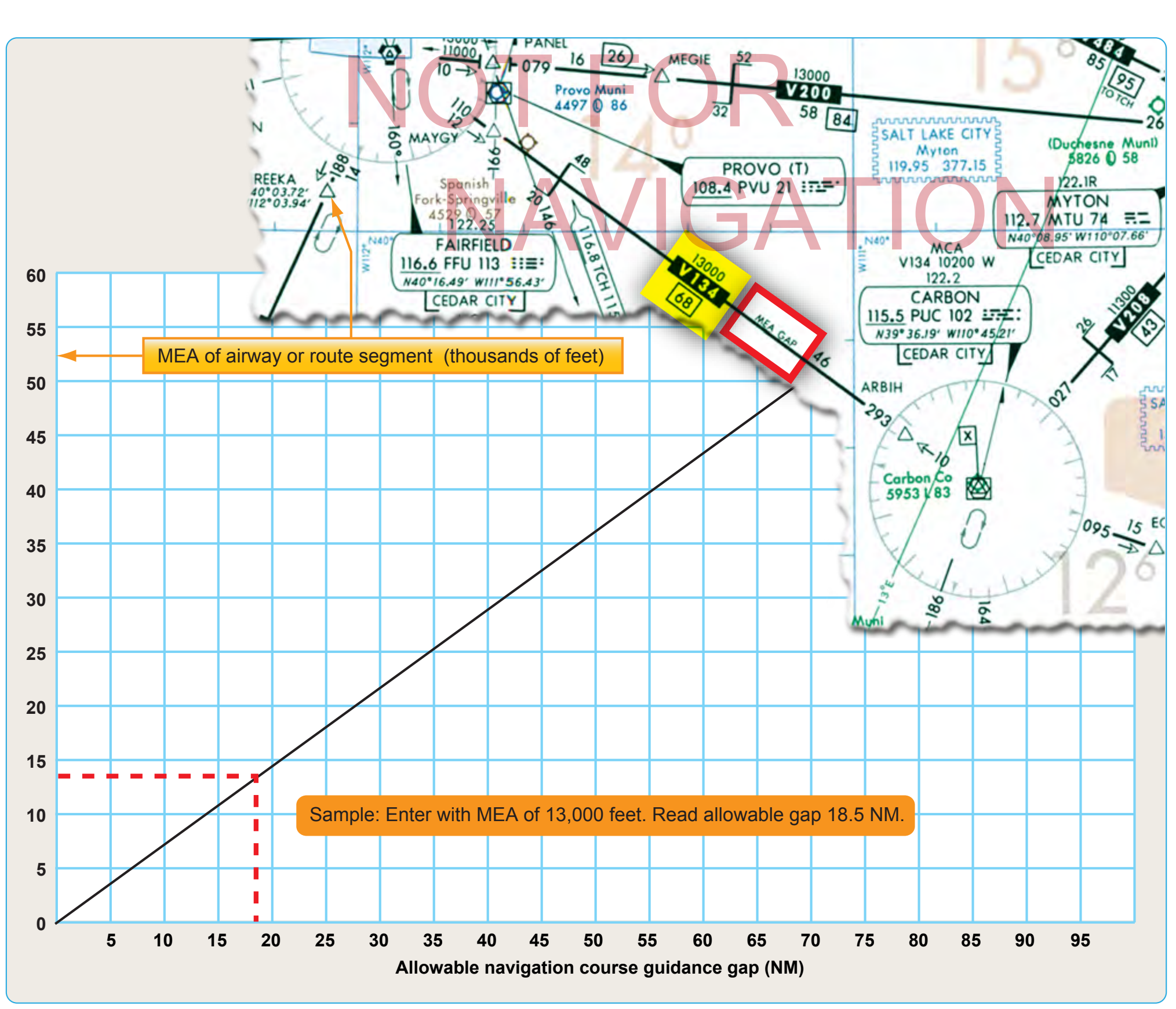
A navigational course guidance gap, referred to as an MEA gap, describes a distance along an airway or route segment where a gap in navigational signal coverage exists. The navigational gap may not exceed a specific distance that varies directly with altitude, from 0 NM at sea level to 65 NM at 45,000 feet MSL and not more than one gap may exist in the airspace structure for the airway or route segment. Additionally, a gap usually does not occur at any airway or route turning point. To help ensure the maximum amount of continuous positive course guidance available when flying, there are established en route criteria for both straight and turning segments. Where large gaps exist that require altitude changes, MEA “steps” may be established at increments of not less than 2,000 feet below 18,000 feet MSL, or not less than 4,000 feet at 18,000 MSL and above, provided that a total gap does not exist for the entire segment within the airspace structure. MEA steps are limited to one step between any two facilities to eliminate continuous or repeated changes of altitude in problem areas. The allowable navigational gaps pilots can expect to see are determined, in part, by reference to the graph depicted in Figure 2-49. Notice the en route chart excerpt depicting that the MEA is established with a gap in navigation signal coverage northwest of the Carbon VOR/DME on V134. At the MEA of 13,000, the allowable navigation course guidance gap is approximately 18.5 NM, as depicted in Figure 2-49. The navigation gap area is not identified on the chart by distances from the navigation facilities. Proper flight planning will help pilots prepare for MEA gaps by insuring that appropriate maps are available as they may need to dead reckon through the gap. Calculating the ground track (with adjustments for winds) before and after the gap will also help to stay on course when navigational course guidance is not available.
NAVAID Accuracy Check
The CFRs and good judgment dictate that the equipment of aircraft flying under IFR be within a specified tolerance before taking off. When approved procedures are available, they should be used for all equipment inspections.
VOR Accuracy
VOR accuracy can be checked by using any of the following methods: VOR test facility signal (VOT), VOR checkpoint signs, dual VOR check, or airborne VOR check.
VOT
The VOT is an approved test signal and is located on an airport. This enables the pilot to check the VOR accuracy from the flight deck before takeoff. Listed below are the steps used for a VOT:
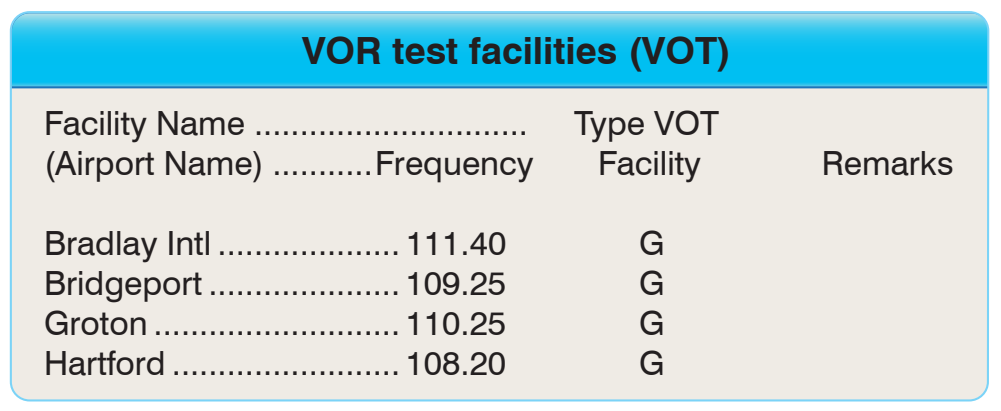
- Tune the VOR receiver to the VOT frequency. VOT frequencies can be found in the CS. [Figure 2-50] These frequencies are coded with a series of Morse code dots or a continuous 1020-cycle tone.