Chapter 2
En Route Operations
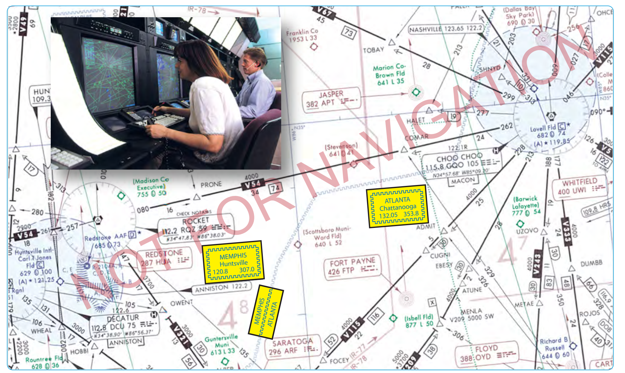
The FAA National Aeronautical Information Services publishes en route charts depicting Centers and sector frequencies. [Figure 2-13] During handoff from one Center to another, the previous controller assigns a new frequency. In cases where flights may be out of range, the Center frequencies on the face of the chart are very helpful. In Figure 2-13, notice the boundary between Memphis, Tennessee and Atlanta, Georgia Centers, and the remote sites with discrete very high frequency (VHF) and ultra high frequency (UHF) for communicating with the appropriate ARTCC. These Center frequency boxes can be used for finding the nearest frequency within the aircraft range. They also can be used for making initial contact with the Center for clearances. The exact location for the Center transmitter is not shown, although the frequency box is placed as close as possible to the known location.
During the en route phase, as a flight transitions from one Center facility to the next, a handoff or transfer of control is required as previously described. The handoff procedure is similar to the handoff between other radar facilities, such as departure or approach control. During the handoff, the controller whose airspace is being vacated issues instructions that include the name of the facility to contact, appropriate frequency, and other pertinent remarks.
Accepting radar vectors from controllers does not relieve pilots of their responsibility for safety of flight. Pilots must maintain a safe altitude and keep track of their position, and it is their obligation to question controllers, request an amended clearance, or, in an emergency, deviate from their instructions if they believe that the safety of flight is in doubt. Keeping track of altitude and position when climbing, and during all other phases of flight, are basic elements of situational awareness (SA). Aircraft equipped with an enhanced ground proximity warning system (EGPWS), terrain awareness and warning system (TAWS), or traffic alert and collision avoidance system (TCAS) help pilots detect and/or correct for potential unsafe proximities to other aircraft and increases pilot(s) situational awareness. Regardless of equipment, pilots must always maintain SA regarding their location and the location of traffic in their vicinity.
High Altitude Area Navigation Routing
Special high altitude routes allow pilots routing options for flight within the initial high altitude routing (HAR) Phase I expansion airspace. Pilots are able to fly user-preferred routes, referred to as non-restrictive routing (NRR), between specific fixes described by pitch (entry into) and catch (exit out of) fixes in the HAR airspace. Pitch points indicate an end of departure procedures, preferred IFR routings, or other established routing programs where a flight can begin a segment of NRR. The catch point indicates where a flight ends a segment of NRR and joins published arrival procedures, preferred IFR routing, or other established routing programs.
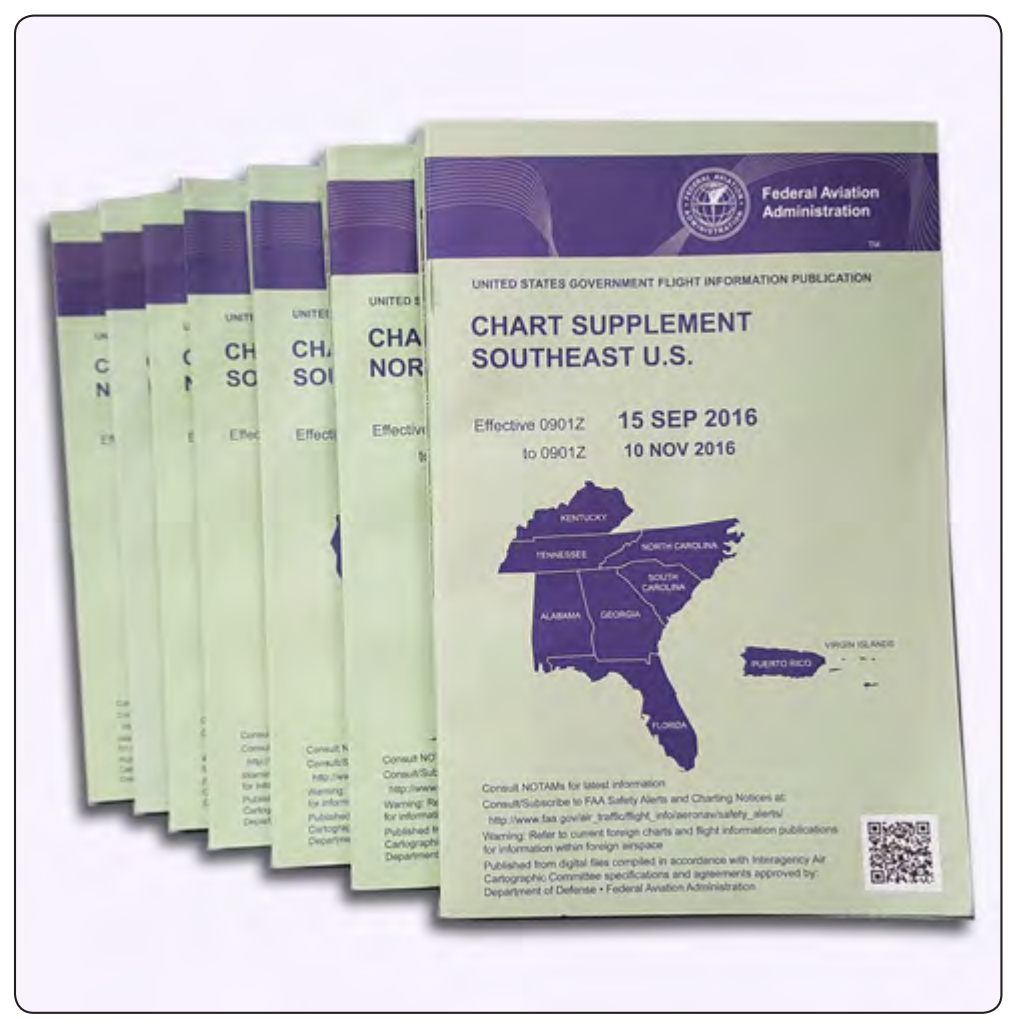
The HAR Phase I expansion airspace is defined as that airspace at and above FL 350 in fourteen of the western and southern ARTCCs. The airspace includes Minneapolis (ZMP), Chicago (ZAU), Kansas City (ZKC), Denver (ZDV), Salt Lake City (ZLC), Oakland (ZOA), Seattle Centers (ZSE), Los Angeles (ZLA), Albuquerque (ZAB), Fort Worth (ZFW), Memphis (ZME), and Houston (ZHU). Jacksonville (ZJX) and Miami (ZMA) are included for east-west routes only. To develop a flight plan, select pitch and catch points which can be found in the Chart Supplement (CS) based upon your desired route across the Phase I airspace. Filing requirements to pitch points, and from catch points, remain unchanged from current procedures. For the portion of the route between the pitch and catch points, NRR is permitted. Where pitch points for a specific airport are not identified, aircraft should file an appropriate departure procedure (DP), or any other user preferred routing prior to the NRR portion of their routing. Where catch points for a specific airport are not identified aircraft should file, after the NRR portion of their routing, an appropriate arrival procedure or other user preferred routing to their destination.
Additionally, information concerning the location and schedule of special use airspace (SUA) and Air Traffic Control Assigned Airspace (ATCAA) can be found at http:// [sua.faa.gov](http://sua.faa.gov). ATCAA refers to airspace in the high altitude structure supporting military and other special operations. Pilots are encouraged to file around these areas when they are scheduled to be active, thereby avoiding unplanned reroutes around them.
In conjunction with the HAR program, area navigation (RNAV) routes have been established to provide for a systematic flow of air traffic in specific portions of the en route flight environment. The designator for these RNAV routes begin with the letter Q, for example, Q-501. Where those routes aid in the efficient orderly management of air traffic, they are published as preferred IFR routes.
Preferred IFR Routes
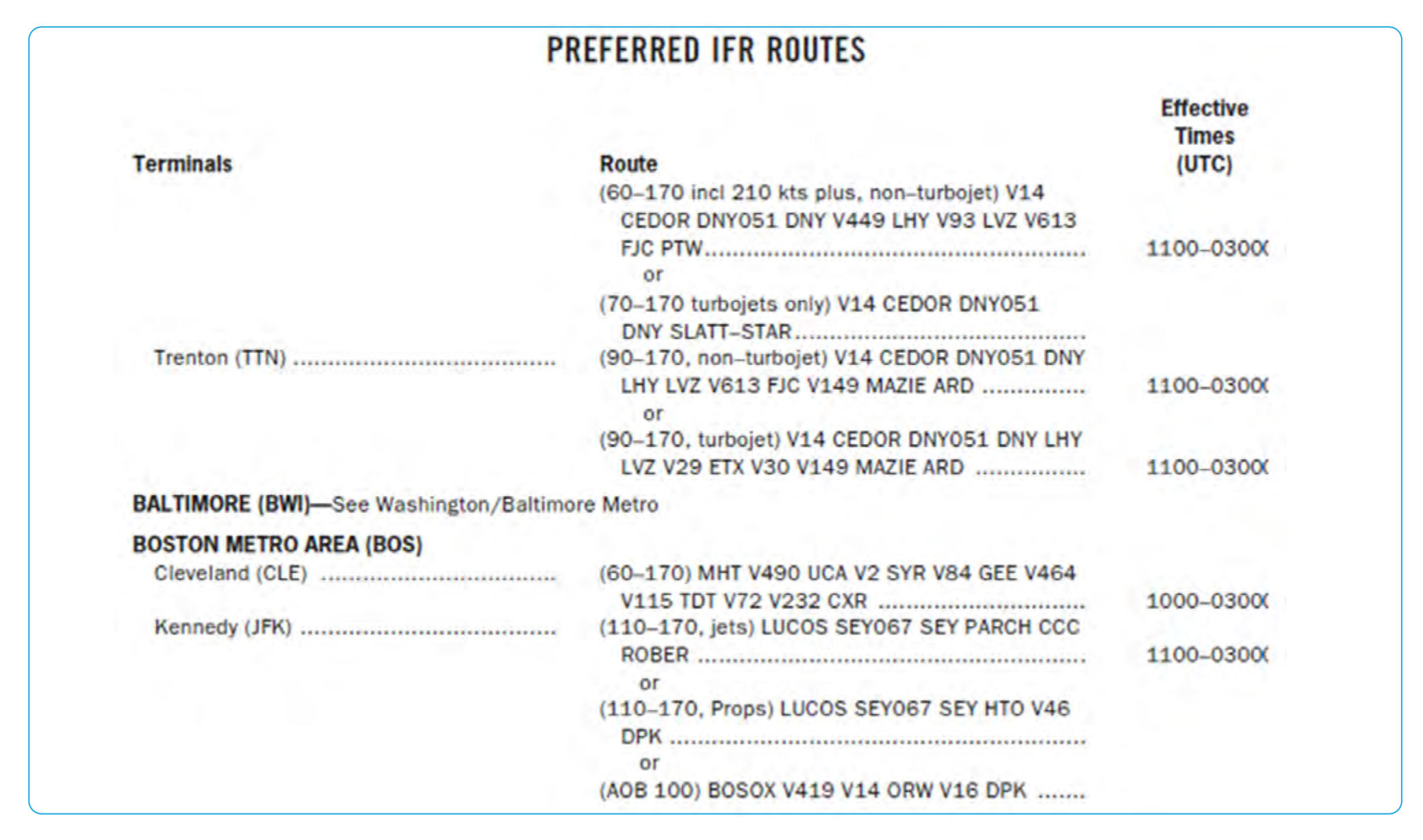
Preferred IFR routes are established between busier airports to increase system efficiency and capacity. They normally extend through one or more ARTCC areas and are designed to achieve balanced traffic flows among high density terminals. IFR clearances are issued on the basis of these routes except when severe weather avoidance procedures or other factors dictate otherwise. Preferred IFR routes are listed in the CS and can also be found on [www.fly.faa.gov](http://www.fly.faa.gov), which requires entering the following data: departure airport designator, destination, route type, area, aircraft types, altitude, route string, direction, departure ARTCC, and arrival ARTCC. [Figure 2-14] If a flight is planned to or from an area having such routes but the departure or arrival point is not listed in the CS, pilots may use that part of a preferred IFR route that is appropriate for the departure or arrival point listed. Preferred IFR routes are correlated with departure procedures (DPs) and STARs and may be defined by airways, jet routes, direct routes between NAVAIDs, waypoints, NAVAID radials/ distance measuring equipment (DME), or any combinations thereof.
Preferred IFR routes are published in the CS for the low and high altitude stratum. If they begin or end with an airway number, it indicates that the airway essentially overlies the airport and flights normally are cleared directly on the airway. Preferred IFR routes beginning or ending with a fix indicate that pilots may be routed to or from these fixes via a SID route, radar vectors, or a STAR. Routes for major terminals are listed alphabetically under the name of the departure airport. Where several airports are in proximity, they are listed under the principal airport and categorized as a metropolitan area (e.g., New York Metro Area). One way preferred IFR routes are listed is numerically, showing the segment fixes and the direction and times effective. Where more than one route is listed, the routes have equal priority for use. Official location identifiers are used in the route description for very high frequency omnidirectional ranges (VORs) and very high frequency omnidirectional ranges/tactical air navigation (VORTACs), and intersection names are spelled out. The route is direct where two NAVAIDs, an intersection and a NAVAID, a NAVAID and a NAVAID radial and distance point, or any navigable combination of these route descriptions follow in succession.
A system of preferred IFR routes helps pilots, flight crews, and dispatchers plan a route of flight to minimize route changes, and to aid in the efficient, orderly management of air traffic using Federal airways. Preferred IFR routes are designed to serve the needs of airspace users and to provide for a systematic flow of air traffic in the major terminal and en route flight environments. Cooperation by all pilots in filing preferred routes results in fewer air traffic delays and better efficiency for departure, en route, and arrival air traffic service. [Figure 2-15]
Substitute Airway or Route Structures
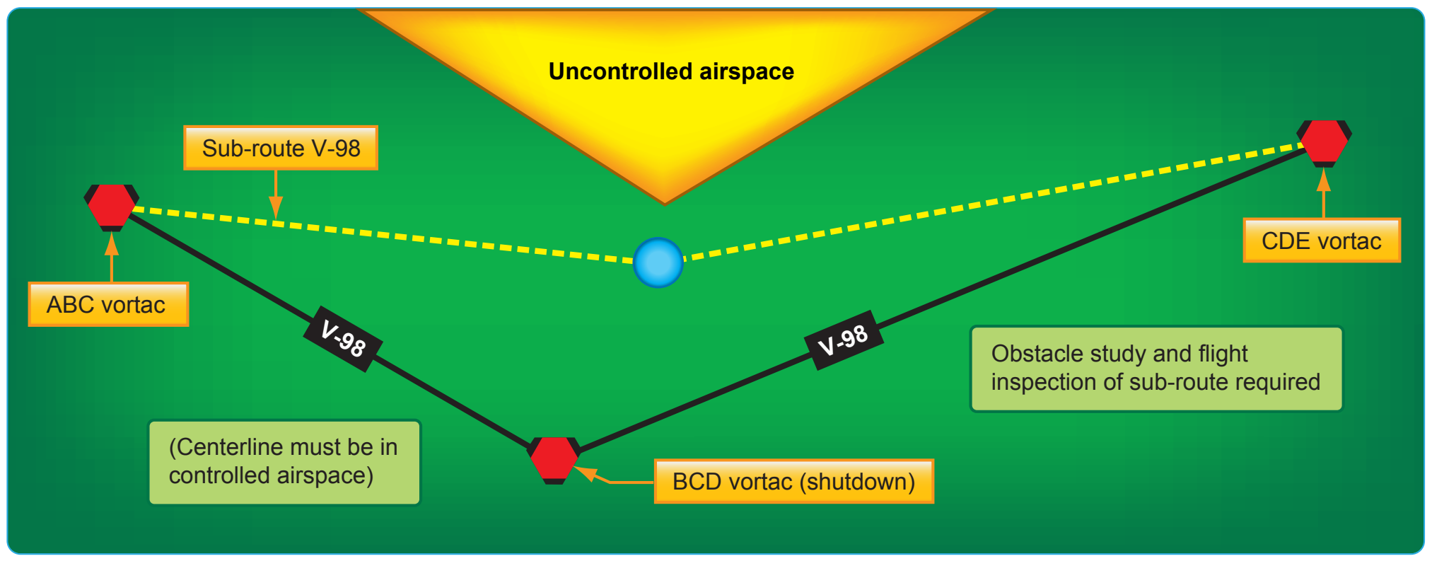
ARTCCs are responsible for specifying essential substitute airway or route segments (sub-routes) and fixes for use during scheduled or unscheduled VOR/VORTAC shutdowns. Scheduled shutdowns of navigational facilities require planning and coordination to ensure an uninterrupted flow of air traffic. Aeronautical Information Services, in coordination with the ARTCCs, determine when the length of outages or other factors require publication of sub-routes and Flight Program Operations (AJW-3) provides flight inspection services, obstacle clearance verification, certification, and final approval of substitute routes.
Substitute Airway En Route Flight Procedures
A schedule of proposed facility shutdowns within the region is maintained and forwarded as far in advance as possible to enable the substitute routes to be published. Substitute routes are normally based on VOR/VORTAC facilities established and published for use in the appropriate altitude strata. In the case of substitute routes in the upper airspace stratum, it may be necessary to establish routes by reference to VOR/VORTAC facilities used in the low altitude system. Non-directional (radio) beacon (NDB) facilities may only be used where VOR/VORTAC coverage is inadequate and ATC requirements necessitate use of such NAVAIDs. Where operational necessity dictates, NAVAIDs may be used beyond their standard service volume (SSV) limits that define the reception limits of unrestricted NAVAIDs, which are usable for random/unpublished route navigation, provided that the routes can be given adequate frequency protection.