Chapter 2
En Route Operations
IFR En Route Low Altitude Chart
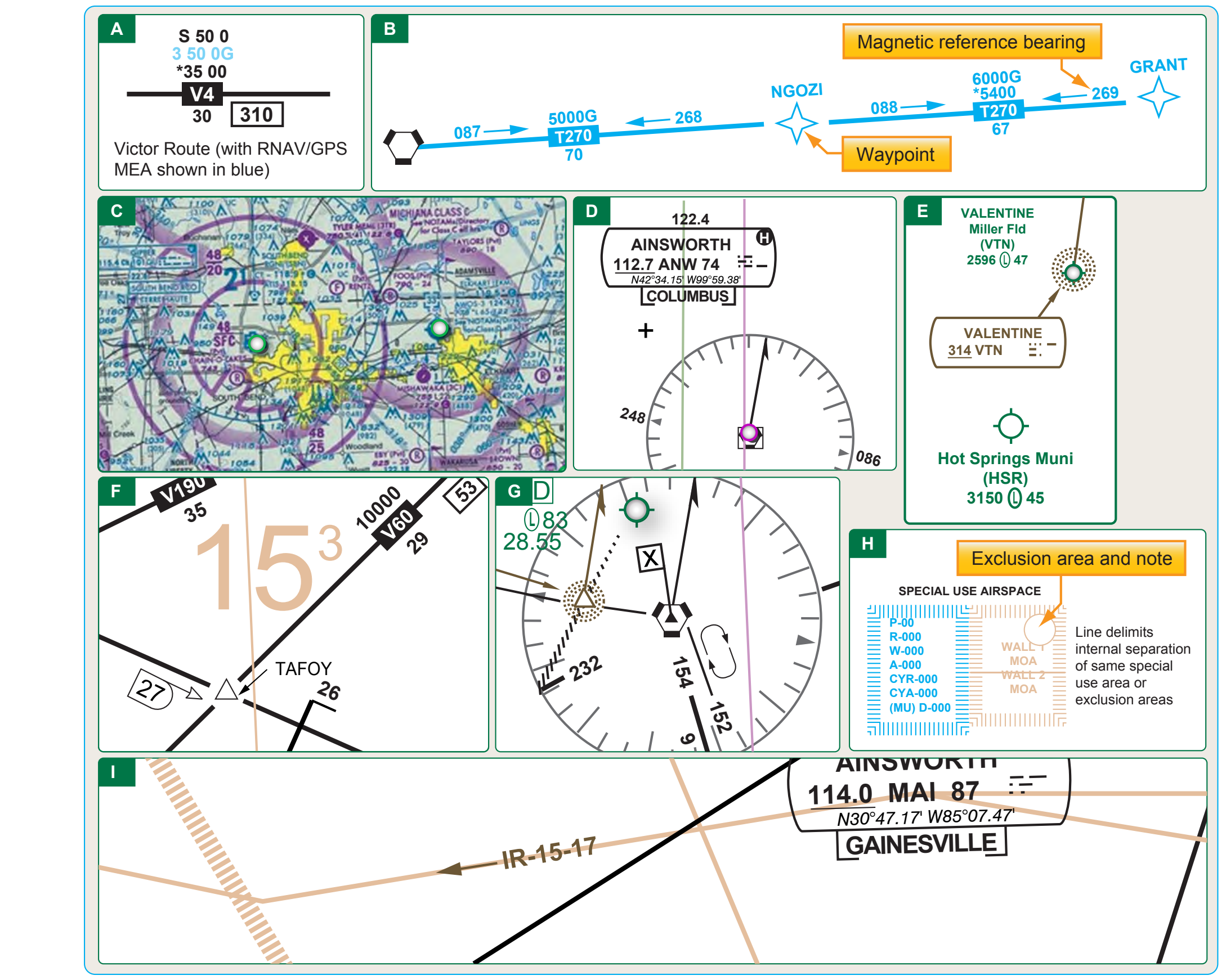
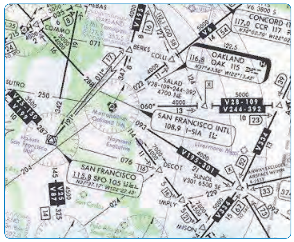
En route low altitude charts provide aeronautical information for navigation under IFR conditions below 18,000 feet MSL. Low altitude charts [Figure 2-25] include the following information:
- Airways [Figure 2-25A]
- RNAV routes [Figure 2-25B]
- Limits of controlled airspace [Figure 2-25C]
- VHF radio aids to navigation (frequency, identification, channel, geographic coordinates) [Figure 2-25D]
- Airports that have an instrument approach procedure or a minimum 3,000 foot hard surface runway [Figure 2-25E]
- Off-route obstruction clearance altitudes (OROCA) [Figure 2-25F]
- Reporting points [Figure 2-25G]
- Special use airspace areas [Figure 2-25H]
- Military training routes [Figure 2-25I]
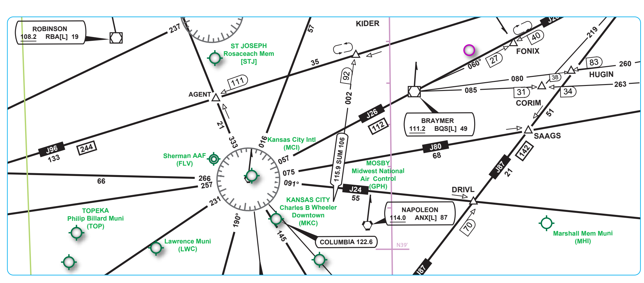
IFR aeronautical charts depict VOR airways (airways based on VOR or VORTAC NAVAIDs) in black, identified by a “V” (Victor) followed by the route number (e.g., V12). [Figure 2-26] LF/MF airways (airways based on LF/MF NAVAIDs) are sometimes referred to as colored airways because they are identified by color name and number (e.g., Amber One, charted as A1). Green and red airways are plotted east and west, and amber and blue airways are plotted north and south. Regardless of their color identifier, LF/MF airways are depicted in brown. [Figure 2-27]
Airway/route data, such as the airway identifications, bearings or radials, mileages, and altitude (e.g., MEA), minimum obstacle clearance altitude (MOCA), and MAA, are shown aligned with the airway and in the same color as the airway. [Figure 2-26]
All airways/routes that are predicated on VOR or VORTAC NAVAIDs are defined by the outbound radial from the NAVAID. Airways/routes that are predicated on LF/MF NAVAIDs are defined by the inbound bearing.
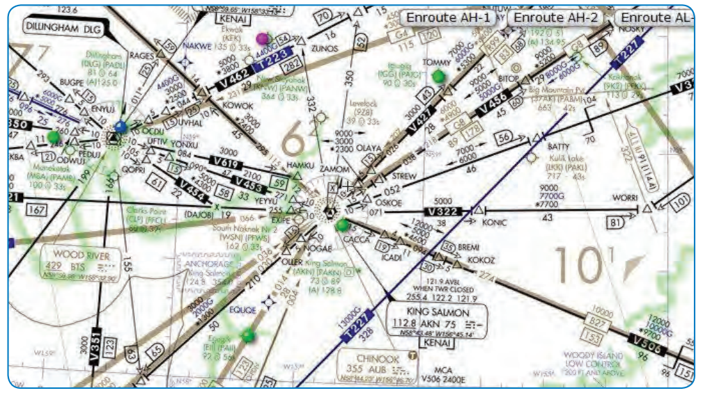
New low altitude RNAV routes have been created by the FAA. RNAV routes provide more direct routing for IFR aircraft and enhance the safety and efficiency of the NAS. In order to utilize these routes, aircraft must be equipped with IFR approved GNSS. In Alaska, when using RNAV routes, the aircraft must be equipped with Technical Standing Order (TSO)-145a and 146a equipment.
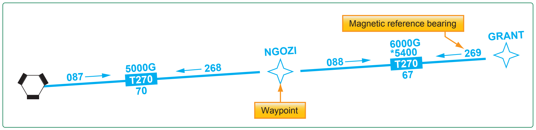
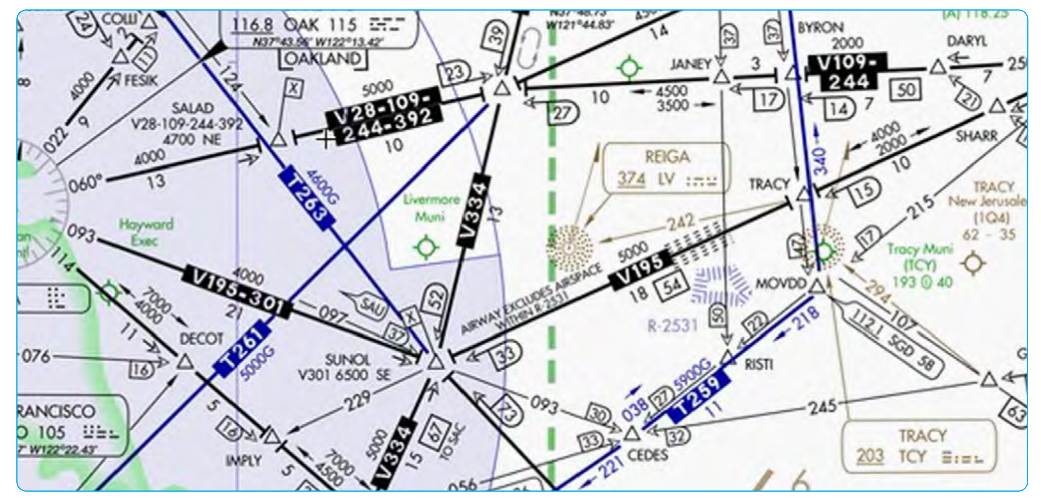
Low altitude RNAV only routes are identified by the letter “T” prefix, followed by a three digit number (T-200 to T-500). RNAV routes are depicted in aeronautical blue, as well as the RNAV route data, which includes the following [Figure 2-28]:
- Route line
- Identification boxes
- Mileages
- Waypoints
- Waypoint names
- Magnetic reference bearings
- MEAs
Magnetic reference bearings are shown originating from a waypoint, fix/reporting point, or NAVAID. A GNSS MEA for each segment is established to ensure obstacle clearance and communications reception. All MEAs are identified with a “G” suffix. [Figure 2-29]
Joint Victor/RNAV routes are depicted using black for the victor airways and blue for the RNAV routes, and the identification boxes for each are shown adjacent to one another. Magnetic reference bearings are not shown. MEAs are stacked in pairs or in two separate columns, GNSS and Victor. On joint routes, or victor routes, RNAV specific information is printed in blue. [Figure 2-30]