Chapter 2
En Route Operations
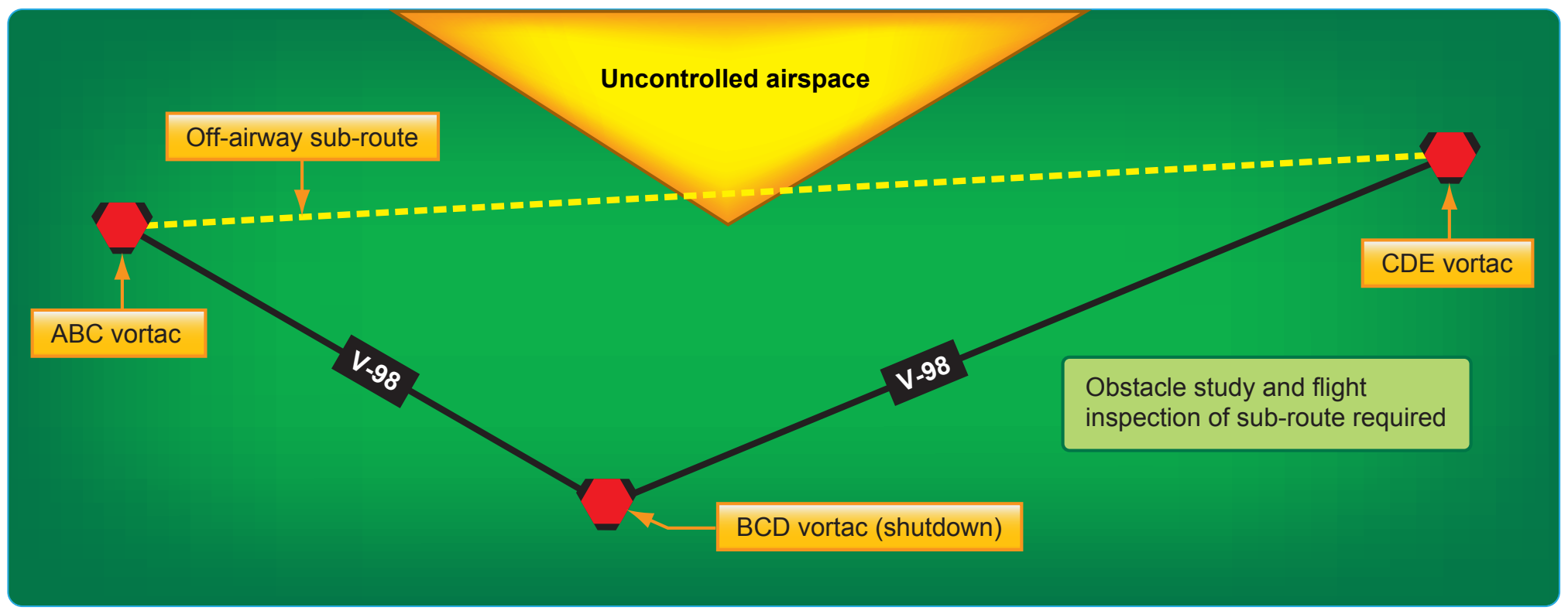
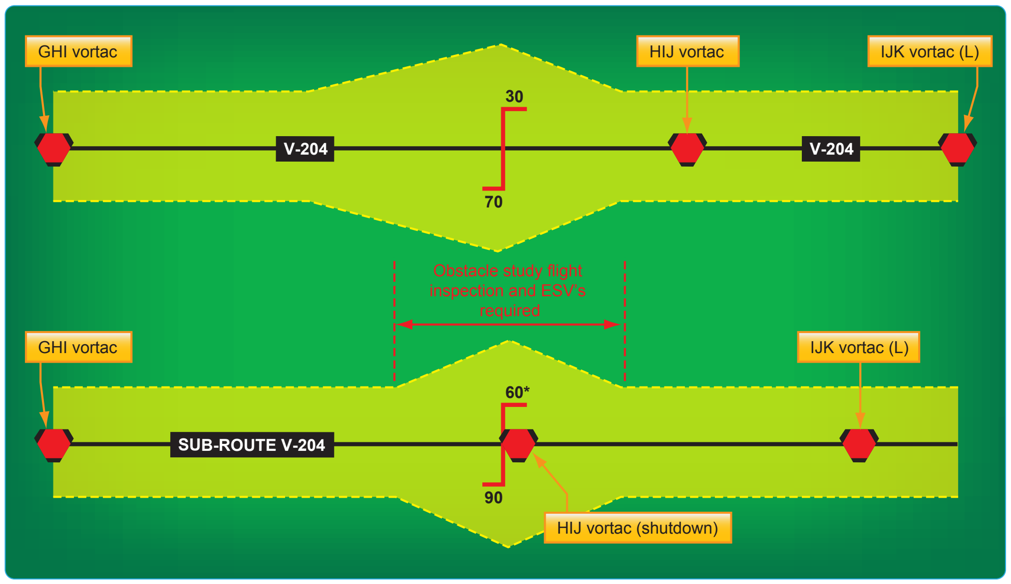
The centerline of substitute routes must be contained within controlled airspace [Figure 2-16], although substitute routes for off-airway routes may not be in controlled air-space. [Figure 2-17] Substitute routes are flight inspected to verify clearance of controlling obstacles and to check for satisfactory facility performance. If substitute routes do not overlie existing routes, or are wider than existing routes, map studies are required to identify controlling obstacles. [Figure 2-18] The format for describing substitute routes is from navigational fix to navigational fix. A minimum en route altitude (MEA) and a maximum authorized altitude (MAA) are provided for each route segment. Temporary reporting points may be substituted for the out-of-service facility and only those other reporting points that are essential for ATC. Normally, temporary reporting points over intersections are not necessary where Center radar coverage exists. A minimum reception altitude (MRA) is established for each temporary reporting point.
Tower En Route Control
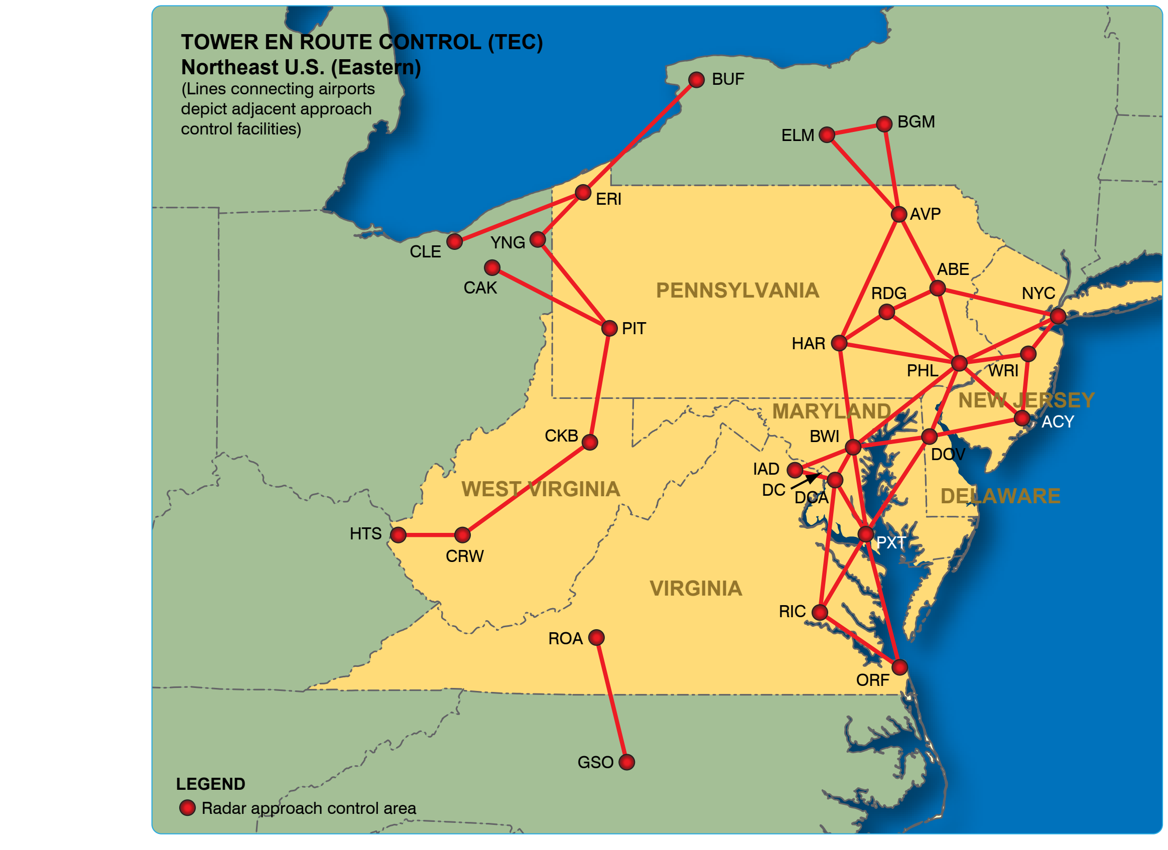
Tower en route control (TEC) is an ATC program available to pilots that provides a service to aircraft proceeding to and from metropolitan areas. It links designated approach control areas by a network of identified routes made up of the existing airway structure of the NAS, which makes it possible to fly an IFR flight without leaving approach control airspace. [Figure 2-19] This service is designed to help expedite air traffic and reduces ATC and pilot communication requirements. The program is generally used by non-turbojet aircraft operating at and below 10,000 feet but a few facilities, such as Milwaukee and Chicago, have allowed turbojets to proceed between city pairs. Participating flights are relatively short with a duration of two hours or less.
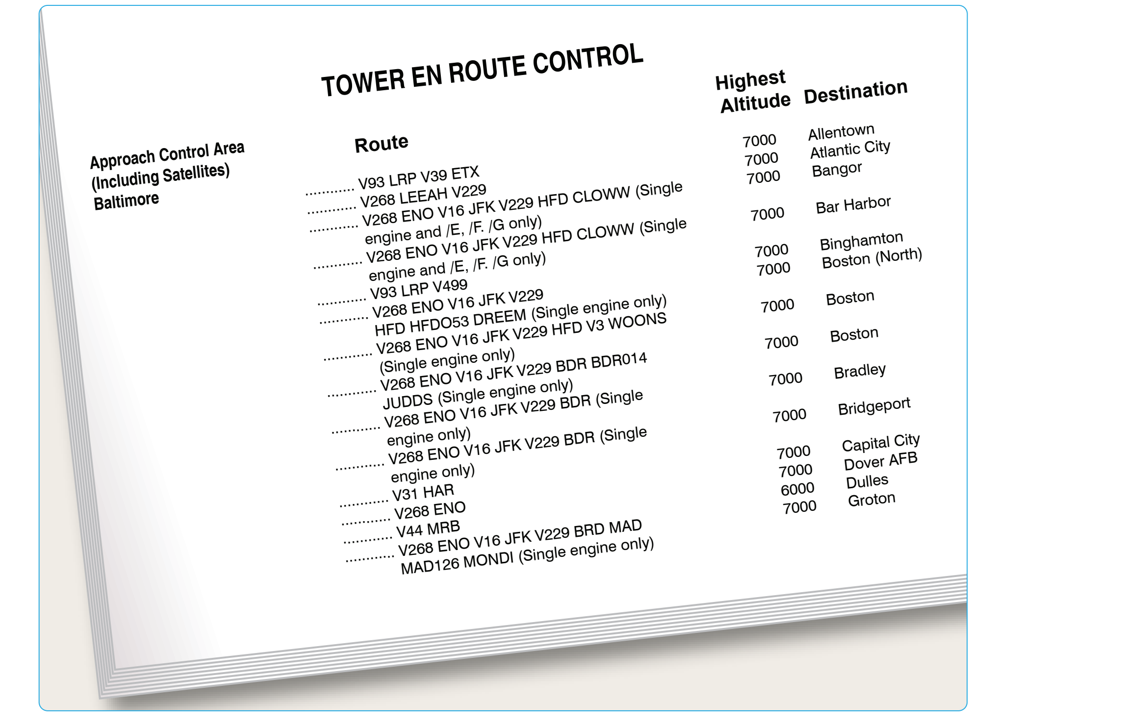
TEC is referred to as tower en route, or tower-to-tower, and allows flight beneath the en route structure. TEC reallocates airspace both vertically and geographically to allow flight planning between city pairs while remaining with approach control airspace. All users are encouraged to use the TEC route descriptions located in the CS when filing flight plans. [Figure 2-20] All published TEC routes are designed to avoid en route airspace, and the majority is within radar coverage.
Tower En Route Control Route Descriptions
The graphic depiction of TEC routes located in the CS is not to be used for navigation or for detailed flight planning because not all city pairs are depicted. The information is intended to show geographic areas connected by TEC. [Figure 2-19] Pilots should refer to the route descriptions for specific flight planning.
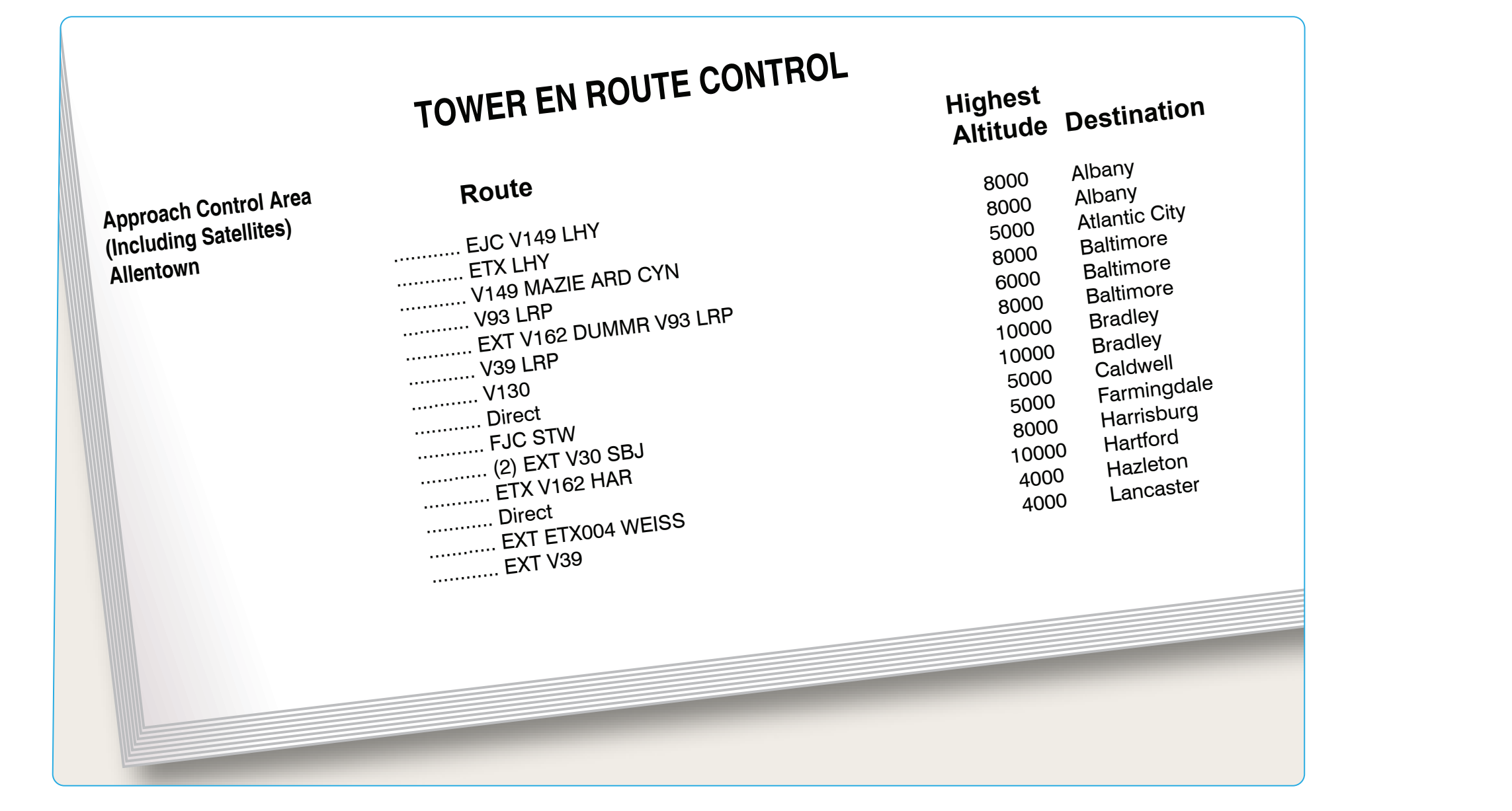
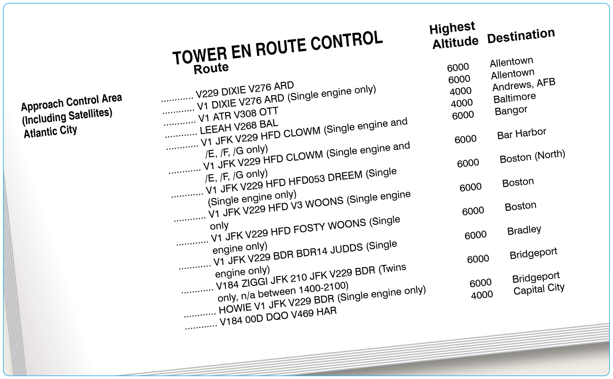
As shown in Figure 2-20, the route description contains four columns of information. The first column is the approach control area within which the departure airport is located, which are listed alphabetically. The second column shows the specific route, airway, or radial that is to be used. The third column shows the highest altitude allowed for the route, and the fourth shows the destination airport, which are also listed alphabetically. When flight planning, it is important to always check current publications for information about the departure and destination airport. Routes are effective only during each respective terminal facilities normal operating hours. Always check NOTAMs to ensure that appropriate terminal facilities are operating for the planned flight time. Altitudes are always listed in thousands of feet. ATC may request that the pilot changes altitude while in flight in order to maintain the flight within approach control airspace. ATC provides radar monitoring and, if necessary, course guidance if the highest altitude assigned is below the MEA.
Shown in Figure 2-21, under the second column, the word “Direct” appears as the route when radar vectors are used or no airway exists. This also indicates that a SID or STAR may be assigned by ATC. When a NAVAID or intersection identifier appears with no airway immediately preceding or following the identifier, the routing is understood to be direct to or from that point unless otherwise cleared by ATC. Routes beginning and ending with an airway indicate that the airway essentially overflies the airport, or radar vectors are issued. [Figure 2-21] Where more than one route is listed to the same destination, ensure that the correct route for the type of aircraft classification has been filed. These are denoted after the route in the altitude column using J (jet powered), M (turbo props/special, cruise speed 190 knots or greater), P (non-jet, cruise speed 190 knots or greater), or Q (non-jet, cruise speed 189 knots or less). [Figure 2-22] Although all airports are not listed under the destination column, IFR flights may be planned to satellite airports in the proximity of major airports via the same routing. When filing flight plans, the coded route identifier (i.e., BURL 1, VTUL4, or POML3) may be used in lieu of the route of flight.
Airway and Route System
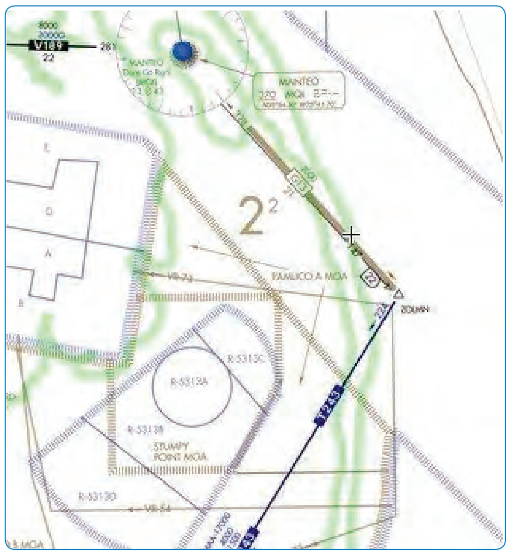
There are three fixed route systems established for air navigation purposes. They are the Federal airway consisting of VOR (low victor airways, high jet routes), NDB (low or medium frequency) and the RNAV route system. To the extent possible, these route systems are aligned in an overlying manner to facilitate transition between each. The majority of the airways are made up of victor airways, jet routes, and RNAV, but some low/medium frequency (L/MF) airways and routes are still being used in Alaska and one other that is located off the coast of North Carolina and is called Green 13 (G13). [Figure 2-23]
Airway/Route Depiction
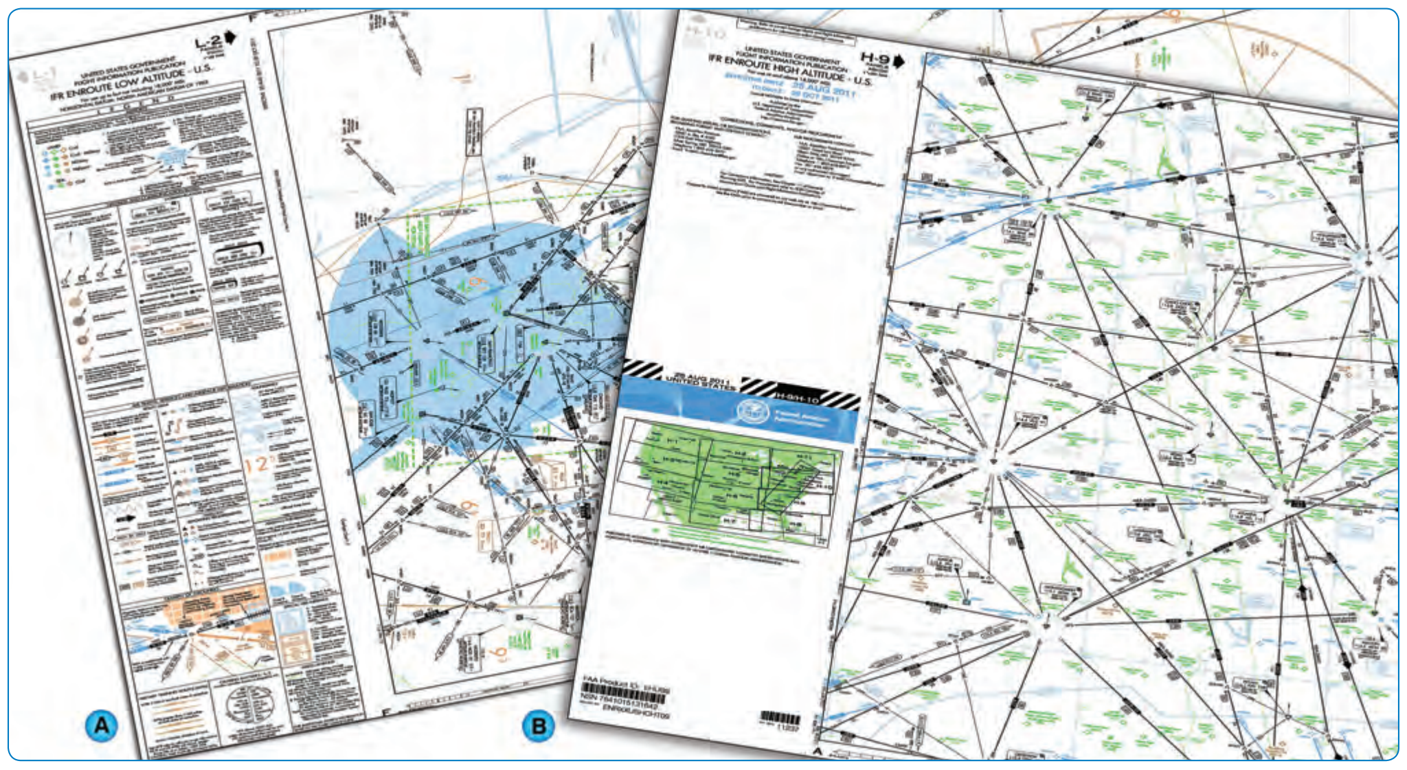
IFR en route charts show all IFR radio NAVAIDs that have been flight-checked by the FAA and are operational. The FAA, Aeronautical Information Services publishes and distributes U.S. Government Civil Aeronautical Charts and flight information publications. IFR en route navigation information is provided on three charts: IFR en route low altitude chart, IFR en route high altitude chart, and Terminal Area Chart (TAC). [Figure 2-24A and B]