
Chapter 4
Approaches
Equipment Requirements
The navigation equipment that is required to join and fly an IAP is indicated by the title of the procedure and notes on the chart. Straight-in IAPs are identified by the navigation system by providing the final approach guidance and the runway with which the approach is aligned (for example, VOR RWY 13). Circling-only approaches are identified by the navigation system by providing final approach guidance and a letter (for example, VOR A). More than one navigation system separated by a slant indicates that more than one type of equipment must be used to execute the final approach (for example, VOR/DME RWY 31). More than one navigation system separated by the word“or” indicates either type of equipment can be used to execute the final approach (for example, VOR or GPS RWY 15).
In some cases, other types of navigation systems, including radar, are required to execute other portions of the approach or to navigate to the IAF (for example, an NDB procedure turn to an ILS, or an NDB in the missed approach, or radar required to join the procedure or identify a fix). When ATC radar or other equipment is required for procedure entry from the en route environment, a note is charted in the plan view of the approach procedure chart (for example, RADAR REQUIRED or AUTOMATIC DIRECTION FINDER (ADF) REQUIRED). When radar or other equipment is required on portions of the procedure outside the final approach segment, including the missed approach, a note is charted in the notes box of the pilot briefing portion of the approach chart (for example, RADAR REQUIRED or DISTANCE MEASURING EQUIPMENT (DME) REQUIRED). Notes are not charted when VOR is required outside the final approach segment. Pilots should ensure that the aircraft is equipped with the required NAVAIDs to execute the approach, including the missed approach. Refer to the AIM paragraph 5-4-5 for additional options with regards to equipment requirements for IAPs.
RNAV systems may be used as a Substitute Means of Navigation when a very high frequency (VHF) Omni-directional Range (VOR), Distance Measuring Equipment (DME), Tactical Air Navigation (TACAN), VOR/TACAN (VORTAC), VOR/DME, non-directional radio beacon (NDB), or compass locator facility including locator outer marker and locator middle marker is out-of-service, i.e., the Navigation Aid (NAVAID) information is not available; an aircraft is not equipped with an automatic direction finder (ADF) or DME; or the installed ADF or DME on an aircraft is not operational. For example, if equipped with a suitable RNAV system, a pilot may hold over an out-of-service NDB. Refer to Advisory Circular 90-108, Use of Suitable RNAV System on Conventional Routes and Procedures, dated March 3, 2011 for additional guidance on the proper times and procedures for substituting a RNAV system for means of navigation.
Courses
Traditional Courses
An aircraft that has been cleared to a holding fix and subsequently “cleared…approach,” normally does not receive new routing. Even though clearance for the approach may have been issued prior to the aircraft reaching the holding fix, ATC would expect the pilot to proceed via the holding fix that was the last assigned route, and the feeder route associated with that fix, if a feeder route is published on the approach chart, to the IAF to commence the approach. When cleared for the approach, the published off-airway (feeder) routes that lead from the en route structure to the IAF are part of the approach clearance.
If a feeder route to an IAF begins at a fix located along the route of flight prior to reaching the holding fix, and clearance for an approach is issued, a pilot should commence the approach via the published feeder route. For example, the aircraft would not be expected to overfly the feeder route and return to it. The pilot is expected to commence the approach in a similar manner at the IAF, if the IAF for the procedure is located along the route of flight to the holding fix.
If a route of flight directly to the IAF is desired, it should be so stated by the controller with phraseology to include the words “direct,” “proceed direct,” or a similar phrase that the pilot can interpret without question. When a pilot is uncertain of the clearance, ATC should be queried immediately as to what route of flight is preferred.
The name of an instrument approach, as published, is used to identify the approach, even if a component of the approach aid is inoperative or unreliable. The controller will use the name of the approach as published, but must advise the aircraft at the time an approach clearance is issued that the inoperative or unreliable approach aid component is unusable. (Example: “Cleared ILS RWY 4, glideslope unusable.”)
Area Navigation Courses
RNAV (GPS) approach procedures introduce their own tracking issues because they are flown using an onboard navigation database. They may be flown as coupled approaches or flown manually. In either case, navigation system coding is based on procedure design, including waypoint (WP) sequencing for an approach and missed approach. The procedure design indicates whether the WP is a fly-over (FO) or fly-by (FB), and provides appropriate guidance for each. A FB WP requires the use of turn anticipation to avoid overshooting the next flight segment. A FO WP precludes any turn until the WP is over flown and is followed by either an intercept maneuver of the next flight segment or direct flight to the next WP.
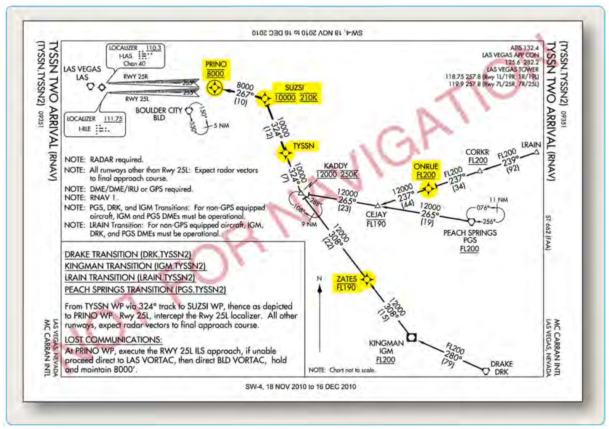
Approach waypoints, except for the missed approach waypoint (MAWP) and the missed approach holding waypoint (MAHWP), are normally FB WPs. Notice that in the plan view in Figure 4-9, there are four FB WPs, but only the circled WP symbol at PRINO is a FO WP. If flying manually to a selected RNAV WP, pilots should anticipate the turn at a FB WP to ensure a smooth transition and avoid overshooting the next flight segment. Alternatively, for a FO WP, no turn is accomplished until the aircraft passes the WP.
There are circumstances when a WP may be coded into the database as both a FB WP and a FO WP, depending on how the WPs are sequenced during the approach procedure. For example, a WP that serves as an IAF may be coded as a FB WP for the approach and as a FO WP when it also serves as the MAWP for the missed approach procedure (MAP). This is just one reason why instrument approaches should be loaded in their entirety from the FMS and not manually built or modified.
Altitudes
Prescribed altitudes may be depicted in four different configurations: minimum, maximum, recommended, and mandatory. The U.S. Government distributes approach charts produced by the FAA. Altitudes are depicted on these charts in the profile view with an underscore or overscore, or both to identify them as minimum, maximum, or mandatory, respectively.
- Minimum altitudes are depicted with the altitude value underscored. Aircraft are required to maintain altitude at or above the depicted value (e.g., 3000).
- Maximum altitudes are depicted with the altitude value overscored. Aircraft are required to maintain altitude at or below the depicted value (e.g., 4800).
- Mandatory altitudes are depicted with the altitude value both underscored and overscored. Aircraft are required to maintain altitude at the depicted value (e.g., 5500).
- Recommended altitudes are depicted without an underscore or overscore.