
Chapter 2
Design and Construction
Conventional (chest mounted) parachute systems utilized a cross-connector at the junction of the riser to the lines of the canopy on each of the front and rear risers. This was so as to maintain drag if one side release before the other. The maximum amount of drag available is required to assure the reserve ripcord activation by the RSL and the release and separation of the off side riser. When applied to the piggy back, these cross connectors would hang up on the bottom of the reserve container preventing separation. Many manufacturers dismissed this need and elected to provide a reserve lanyard that was side sensitive (in that it would activate the reserve if the attached side released and the opposite side did not release). Others moved the lanyard to the base of the riser, which required only one cross connector. This location avoided the possibility of a hang up on the bottom of the reserve and retained the drag integrity.
In recent years and with the widespread acceptance of newer types of AADs, many parachutists feel that they no longer need an RSL. In reality, both systems complement each other. The AAD functions if the individual does not activate the main parachute. However, it is altitude and rate of descent (ROD) dependent. Below a certain altitude, if the ROD is not met, the AAD will not function. Consequently, if a cutaway is performed below the activation altitude, it may take some time for the descending parachutist to reach the ROD necessary to initiate activation, thereby necessitating rapid manual activation of the reserve. However, if an RSL is also installed, it would cause an immediate activation of the reserve as the main parachute disconnects and moves away from the parachutist.
In the last few years, as canopy design has resulted in smaller and more sensitive canopies, many parachutists have elected not to use an RSL. The rationale is that in a violently spinning malfunction, which some of these highly loaded canopies are prone to do, it is preferable to cutaway and regain stability prior to pulling the reserve. This reduces the chance of an entanglement with the deploying reserve. While this scenario has happened, it is a rare occurrence. Statistics show that many lives have been saved by using an RSL.
RSL Designs
There are four primary design configurations of RSLs in use today and are listed below:
- A single-side RSL where the lanyard is attached to only one main riser, usually the left side. [Figure 2-49] Only the one side is required to release to activate the system. This is the most common design in use today due to its simplicity.
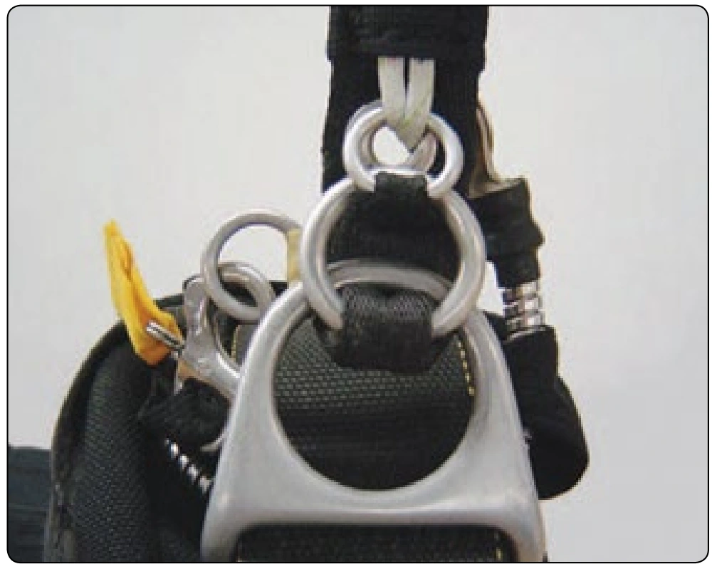
- A dual side RSL where both main risers are connected with a cross connector which is the RSL lanyard. [Figure 2-50A and B] Both risers need to release for the system to activate.
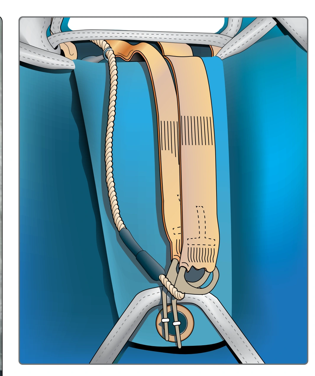
- The LOR system developed by the French. This incorporates two lanyards, one from each riser, that are attached to individual curved pins that secure the reserve container with a dual locking loop. [Figure 2-51] Both risers must be released for the system to function.
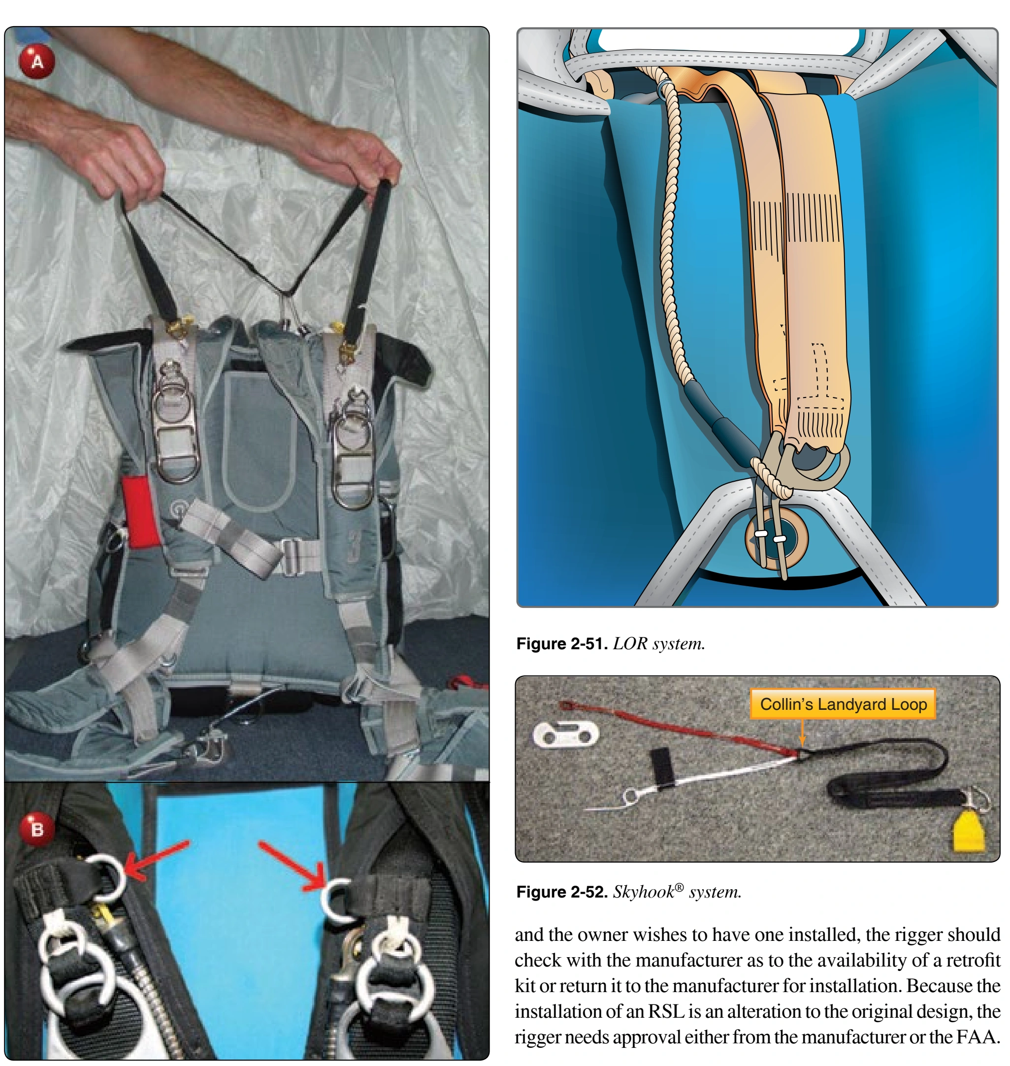
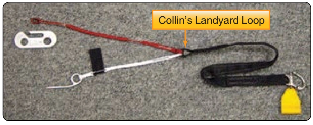
- The Collins Lanyard/Skyhook™ system. This design utilizes a special lanyard that is attached to the bridle of the reserve free bag. [Figure 2-52] Cutting away results in the free bag being pulled directly out of the container by the main risers and results in very little altitude loss.
Since the early 1990s, most (if not all) manufacturers have provided an RSL installation on their equipment either as standard or optional. If the rigger has a system without an RSL Because of the nature of the RSL system, it is imperative that the rigger thoroughly understands the individual concepts. Unless he or she understands this and has the required manufacturer’s instructions, the rigger should not attempt to assemble and pack a system with an RSL installation. The following describes the basic design and function of a single side RSL installation on a one-pin reserve container.
Main Riser Attachment
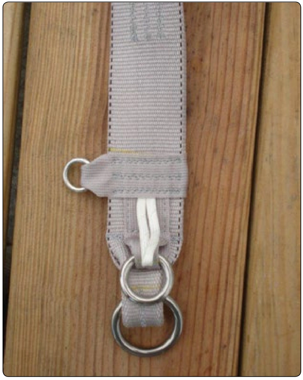
The main risers must have an attachment location for the lanyard. In this example, a small ring is installed near the lower hardware end of the riser on the inboard side. [Figure 2-53] It is desirable to locate the ring as close to the lower end as possible so that the pivot arc of the rise does not load the lanyard. This allows the riser end of the lanyard end to be as short as possible. If there is excess lanyard, it is difficult to stow, and it is possible for the lanyard to become snagged and unseated. It is important that the correct risers with attachment ring be installed. While many risers have a ring installation, not all are installed at the correct location. Consequently, the lanyard length will not match the factory dimensions. This can result in premature reserve activation when the main is deployed.
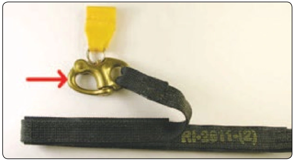
Most RSL lanyard designs have a snap shackle or similar release device mounted at the riser end of the lanyard. [Figure 2-54] This allows the user to disconnect the lanyard under certain circumstances. The most common one involves landing in high winds where the parachutist may wish to cutaway the main canopy to prevent being dragged. If the lanyard were not released, the reserve would be deployed as the main is cutaway.
Ripcord Cable Routing
The routing of the ripcord cable from the handle to the pin determines where the lanyard connects to the cable. Most RSL attachments connect with the ripcord cable either at the yoke area or just above the ripcord pin. Generally, there is a double ring installation where the cable end of the lanyard is located. [Figure 2-55] On this particular installation, the connection is at the shoulder yoke area.