
Chapter 2
Design and Construction
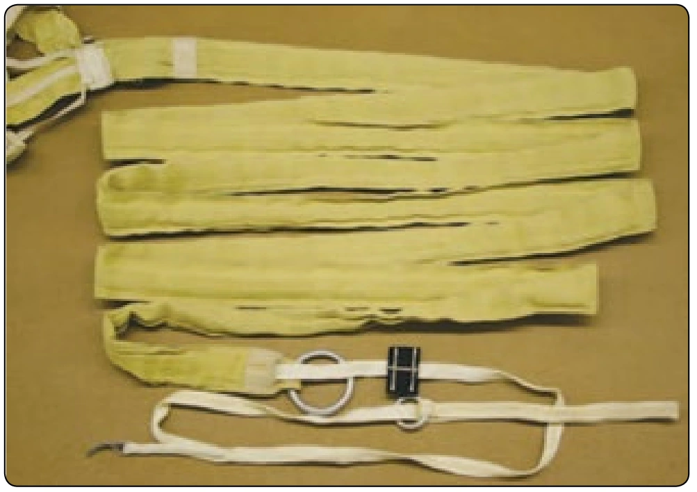
Another method of collapsing the pilot chute is to install a No. 8 grommet in the deployment bag and allow the bag to float on the bridle. After the canopy deploys, the bag slides up the bridle, inverts, and covers the pilot chute. This is commonly called the “poor man’s collapsible pilot chute system.” The drawback to this design is the high wear on the bridle and pilot chute mesh.
Pilot Chutes
A pilot chute is a small parachute that is used to deploy the main or reserve parachute. In the earliest uses of parachutes, the parachute was static line deployed. With the advent of manually operated or “free fall” parachutes, the need for a pilot chute was quickly recognized.
There are two basic types of pilot chutes. The first is the spring-loaded design. This uses a collapsible spring, which is compressed in the parachute container and held closed with the ripcord. When the ripcord is pulled, the pack opens and the pilot chute launches into the airstream. The pilot chute provides drag and pulls the canopy from the pack as the parachutist or load falls away. During this process, the pilot chute also provides tension on the lines of the deploying canopy and helps the opening sequence. Spring-loaded pilot chutes are used primarily for emergency and reserve parachutes. In addition, they are used in military free fall and training systems for the main parachute.
The second type of pilot chute is the “hand deploy” design. This type consists of the pilot chute canopy but does not have a spring to launch it. Instead, the parachutist extracts the folded pilot chute from a pouch or the container and launches it into the airstream. The pack is held closed by a locking pin attached to the bridle of the pilot chute. As the pilot chute inflates, it extracts the pin from the locking loop and pulls the parachute from the pack. The rest of the opening process is similar to the spring-loaded pilot chute. This configuration came into popularity in the mid 1970s and is now the primary method of deployment in skydiving.
Spring-Loaded Pilot Chutes
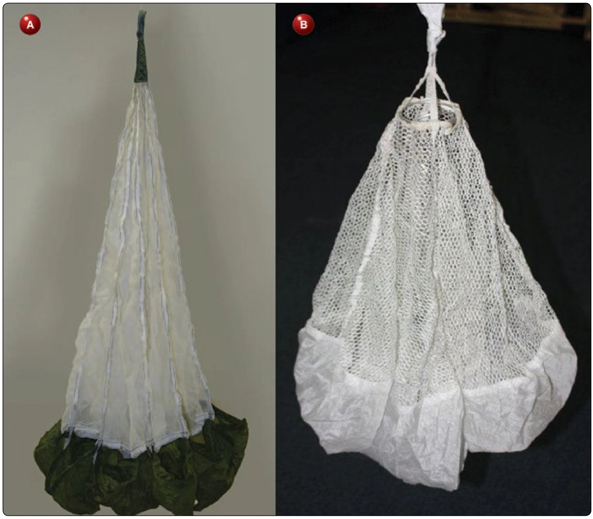
Spring-loaded pilot chutes date from the 1920s. However, it was not until 1940 that the spiral vane pilot chute was invented. This design used a spiral spring that is easy to collapse and pack. The most common type of spiral vane pilot chute used today is the MA-1 model. [Figure 2-40A and B] This is used in several military parachute assemblies. In the early days of skydiving, military pilot chutes, such as the MA-1 and others were popular. Soon commercial designs were introduced that improved on the MA-1 with better launch and drag characteristics. These included the Grabber® and Hot Dog® pilot chutes. Both of these were primarily for use with main parachutes.
With the advent of the hand deploy pilot chute for the main, most of the improvement in spring-loaded pilot chute design has focused on its use in the reserve or emergency parachutes. This has paralleled the improvements in container design and the increased use of AADs. Both of these require better pilot chutes than in the past.
One example for reserve use is the Magnum® pilot chute designed by National Parachute Industries. [Figure 2-41] With its unique shape, it provides maximum drag at low speeds, such as are experienced during cutaways. Its design has been licensed by other manufacturers for use in their assemblies. Additional designs include the Vector II reserve pilot chute and the Stealth pilot chute. The Vector II design is a “ballute” configuration that eliminates the use of mesh. In the event of an unstable launch on its side, the mass of fabric is sufficient to lift the pilot chute and deploy the parachute. The Stealth pilot chute uses a conventional mesh design but has a unique spring/cap configuration that allows the pilot chute to virtually disappear when packed, hence the name. The MA-1 spring with mesh in place of the vanes, and a closed canopy instead of the scalloped canopy provides the best of both worlds: a spring that does not lock up on itself and high drag without the possibility of snag.
Hand Deploy Pilot Chutes
The hand deploy pilot chute was introduced in 1976. There are two types of hand deploy designs. One is the throw-out pilot chute (TOP) configuration. This is the type where the pilot chute pulls the locking pin located on the bridle. [Figure 2-42] The original design had the pilot chute pouch mounted on the belly band. Today, the primary location is an elastic/Spandex® pocket mounted on the bottom of the main container (BOC). [Figure 2-43] Most of the difficulties of this design have to do with pilot chute in tow due to misrouting of the bridle or failure of the pin to extract.
The second type is the pull-out pilot chute (POP) configuration.
This design has the pilot chute packed in the container, which is locked with a straight locking pin attached to a short lanyard and handle. [Figure 2-44A and B] This handle is usually mounted on the bottom corner of the main container. The parachutist grasps the handle and pulls the locking pin from the locking loop and puts the pilot chute into the airstream. The handle is usually attached to the bottom of the pilot chute and as the chute enters the airstream, the jumper loosens his grip on the handle allowing it to be pulled from his or her hand.
This makes for a positive deployment. The main drawback to this system is losing the handle due to it being dislodged while moving around in the aircraft or in the air. Fortunately, the handle does not go far and is easy to obtain because it is on a short lanyard that is tucked up under the side flap..
Automatic Activation Devices (AADs) and Reserve Static Lines (RSLs)
Safety considerations have led to the development of AADs and reserve static line (RSL) systems. These devices allow for automatic deployment of the main or reserve parachutes in the event of an emergency.
Automatic Activation Devices
AADs are devices that activate the parachute automatically. Modern systems combine a barometric sensor with a rate of descent sensor so that the system is fully automatic once turned on and calibrated. The activation may be by either pulling the ripcord pin(s) or cutting the locking loop(s), causing the pilot chute to release. Most older models use a mechanical or pyrotechnic pin pulling technique. Newer models use a pyrotechnic loop cutting design.