
Chapter 2
Design and Construction
For many years, AADs were primarily used by the military and student parachutists. The designs were bulky, expensive, and, to a degree, inconsistent. The installations themselves were cumbersome and awkward. In the early 1990s, a new generation of AADs became available. The CYbernetic Parachute RElease System (CYPRES®) uses modern parachute release technology. It is small, reliable, computer based, and uses a pyrotechnic loop cutter. It has an auto-off feature that turns the unit off after 14 hours of operation to conserve power. It also has the ability to calibrate the unit for operation at altitudes other than the calibrating ground level. Based on these concepts, other companies have developed similar systems and as a result, changed the approach to the design and use of AADs. Today, a good many sport parachutists use an AAD and some countries (rightly or wrongly), mandate their use by all parachutists.
The following describes the operation and installation requirements of the CYPRES® model AA. Other designs, such as the Vigil®, are compatible with these installation requirements.
Operation
The CYPRES® system is a barometrically controlled microprocessor that activates a pyrotechnic cutter that cuts the container locking loop. When calibrated to ground level, the barometric sensor activates the unit firing the cutter when the descending parachutist reaches an altitude of approximately 750 feet above ground level (AGL) and exceeds a rate of descent of 115 feet per second (fps).
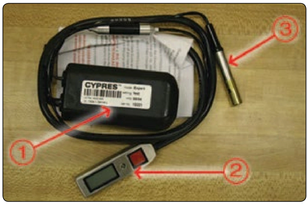
The CYPRES® consists of three parts:
- Battery and processing unit
- Control unit
- Cutter [Figure 2-45]
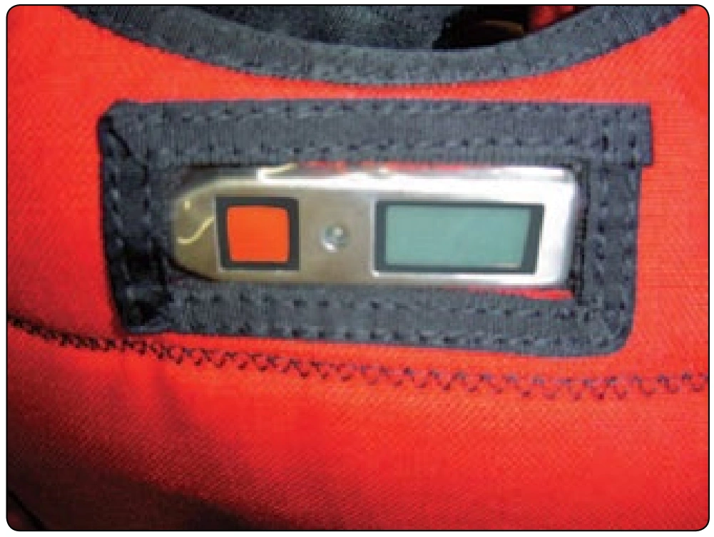
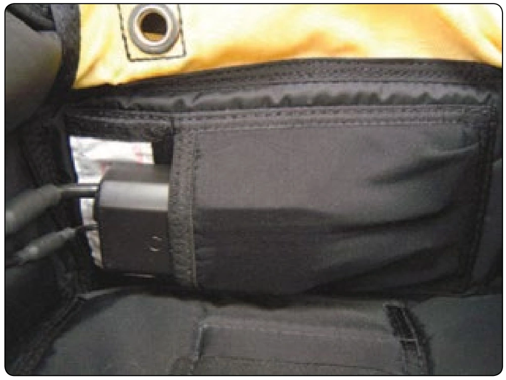
The processing unit is generally located in a stowage pouch installed in the reserve container of the parachute system.
[Figure 2-46] The control unit is contained in a vinyl pocket located either under the pin protector flap or in the upper back pad area. [Figure 2-47]
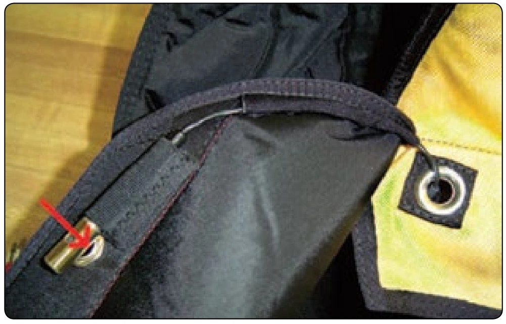
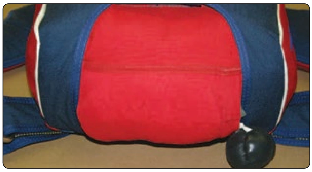
The cutter(s) may be located at the base of the pilot chute or on a flap over the pilot chute. [Figure 2-48] Each parachute system has its own particular requirements, and it is imperative that the rigger have the appropriate manuals for installation.
Reserve Static Line (RSL) Systems
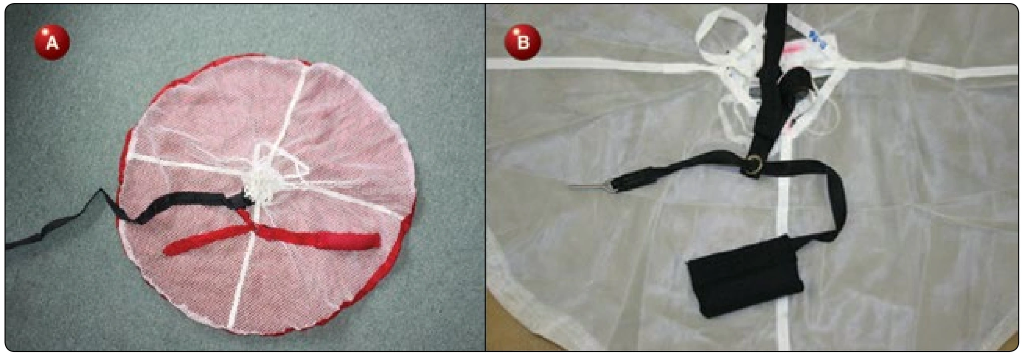
A RSL system is a backup device for activating the reserve after a cutaway is performed. It usually consists of a line, webbing, or cable, which connects one or both main risers to the reserve handle, housing, or cable. The most common design used today has a ring through which the reserve ripcord cable is routed. The riser end attaches to a ring on the riser(s) with a snap shackle for quick release capability. When the risers are jettisoned, the lanyard pulls the cable, releasing the ripcord pin(s), and activates the reserve. This results in a minimum loss of altitude during the cutaway procedure. The use of an RSL has saved many lives over the years due to low cutaways.
Though originally developed in 1964, as the Stevens System, the RSL concept did not become popular until the advent of student piggyback systems and ram-air canopies. Through the use of an RSL system, the student parachutist need only pull the canopy release handle in the event of a partial malfunction, and the main canopy is cutaway and the reserve activates. In 1990, the PIA urged manufacturers to include RSLs as a standard feature on all harness/container systems. Many did and this resulted in an increase of RSL use for several years.