Aviation Training Experts™

handbook

Parachute Rigger Handbook

FAA-H-8083-17A Version 2015 (Change 1)

Chapter 5

Inspection and Packing
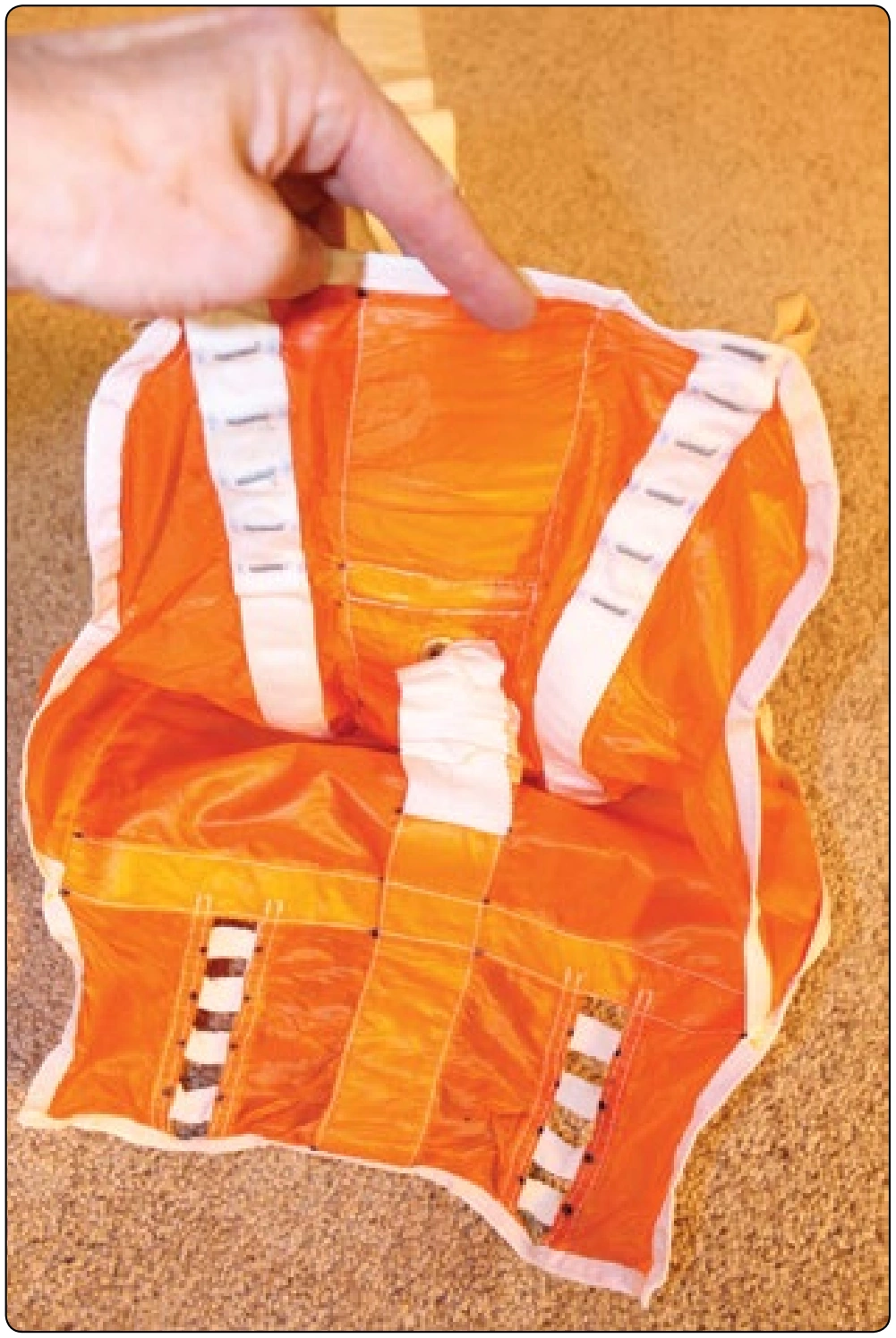
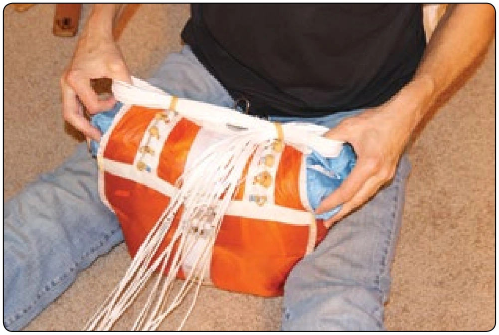
Figure 5-135. Inside the Reserve Speed Bag the buffer tabs form a clear channel for the bottom closing loop.
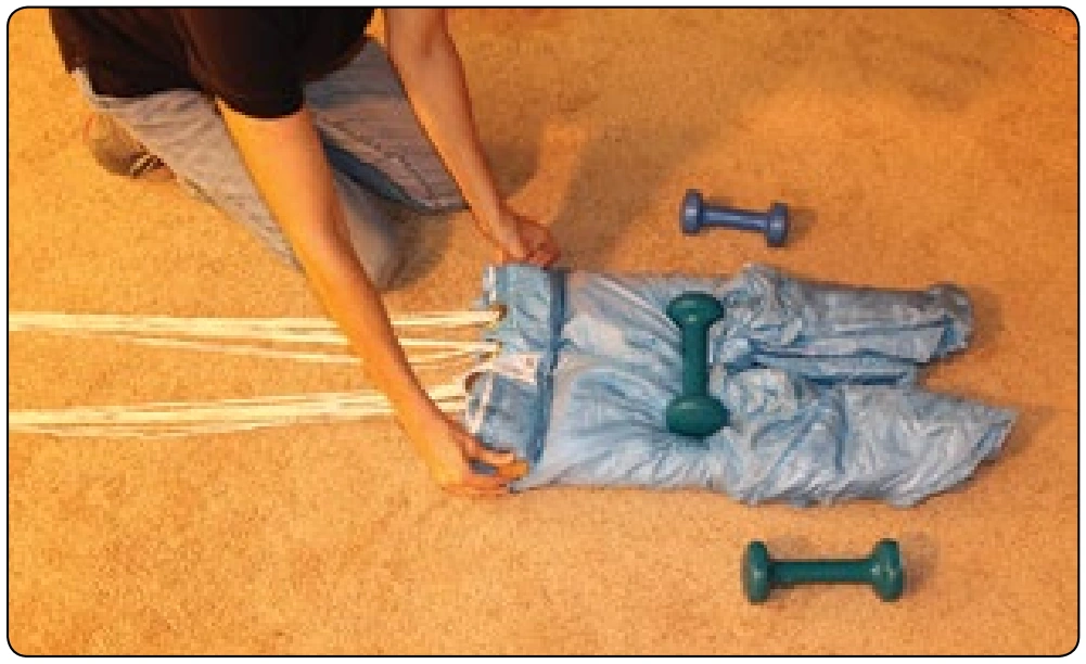
Figure 5-132. The length and width of the S-fold is determined by the width of the container and the distance between the main/reserve vertical partition and the bottom flap grommet.
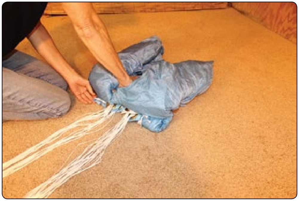
Figure 5-133. Make a second S-fold with the upper part of the canopy on top of the lower part.
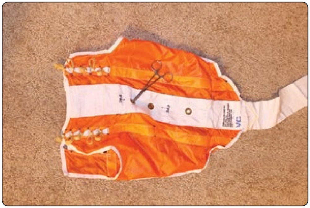
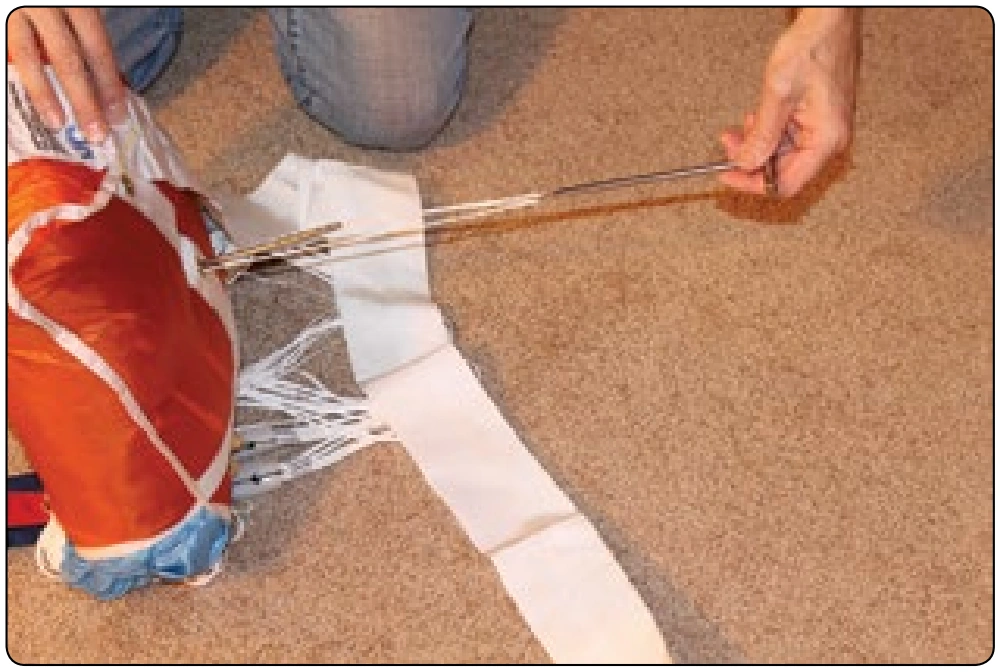
Figure 5-134. Prepare the Reserve Deployment Speed Bag by using a hemostat to pinch the inner buffer tabs together as shown.

Finally, riggers are tasked with noting their name and certificate number on the data card. In many cases, this information is illegible. Riggers who take pride and responsibility in their profession and the work they do have no hesitation in letting the public know who did the work.

Accordingly, many riggers have a permanent ink stamp with their name, certificate number, and seal symbol that they use to stamp the card and then countersign it. This is the mark of a truly professional rigger. While the seal symbol is not required on the data card, it allows anyone to check the signature against the seal on the parachute.

Chapter Summary

It is the responsibility of the attending rigger to ensure that the components of the approved parachute system are compatible in terms of shock load capability. This may be as simple as reading and comparing the TSO/Data Label that is permanently attached to the reserve canopy and the harness. This information may also be found in the respective
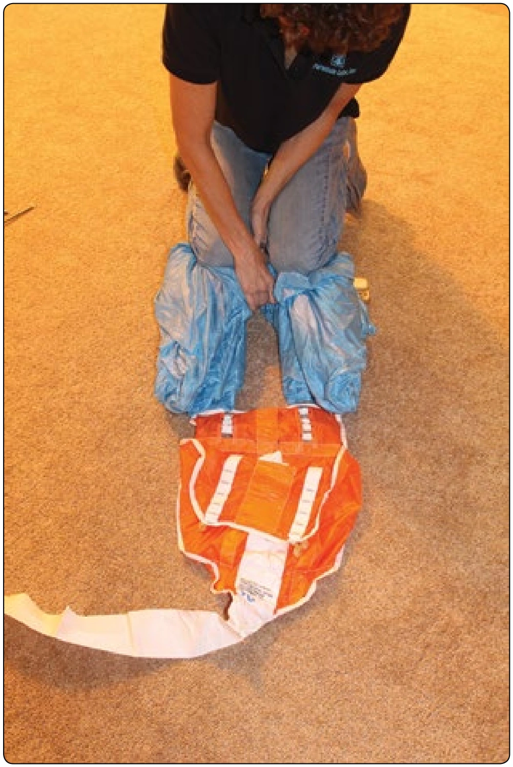
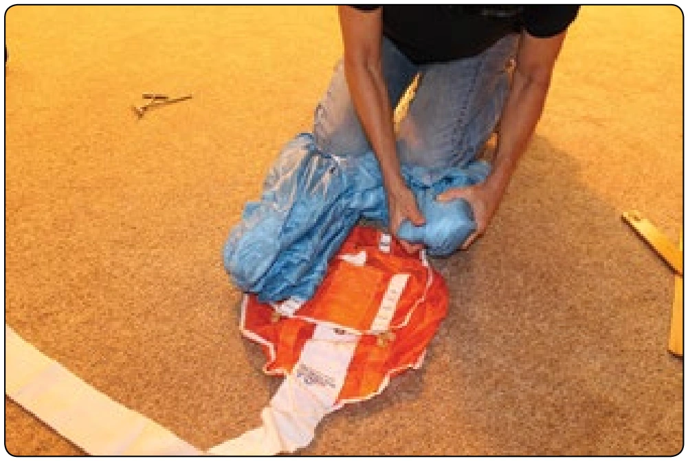
Figure 5-136. The S-folds go below the buffer tabs when the canopy is in the bag.
Figure 5-137. Fold the ears under and pull the bag over the canopy.

Owners Manuals. If in doubt, call the manufacturer(s). Size compatibility, which may affect reserve bag extraction force, is of the utmost importance. In their zeal to make rigs more windproof, some manufacturers have created containers that require more force to pull the bag from the container, due to stiffer riser covers, boxing at the top of the container, and longer cantilever pin protector flaps. Such rigs should not be overstuffed. Reserve pilot chutes should be in new condition to provide maximum drag.
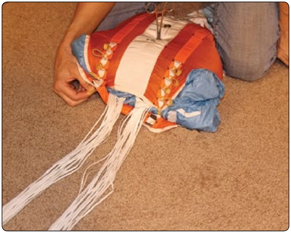
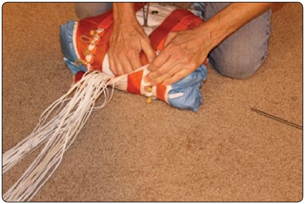
Figure 5-138. Use the flaps of the bag to control the canopy and help push it into the bag.
Figure 5-139. The top flap closes first so that the rubber bands come through the slots in the bottom flap.
Figure 5-140. Stow the lines from top to bottom. Each stow is locking stow.
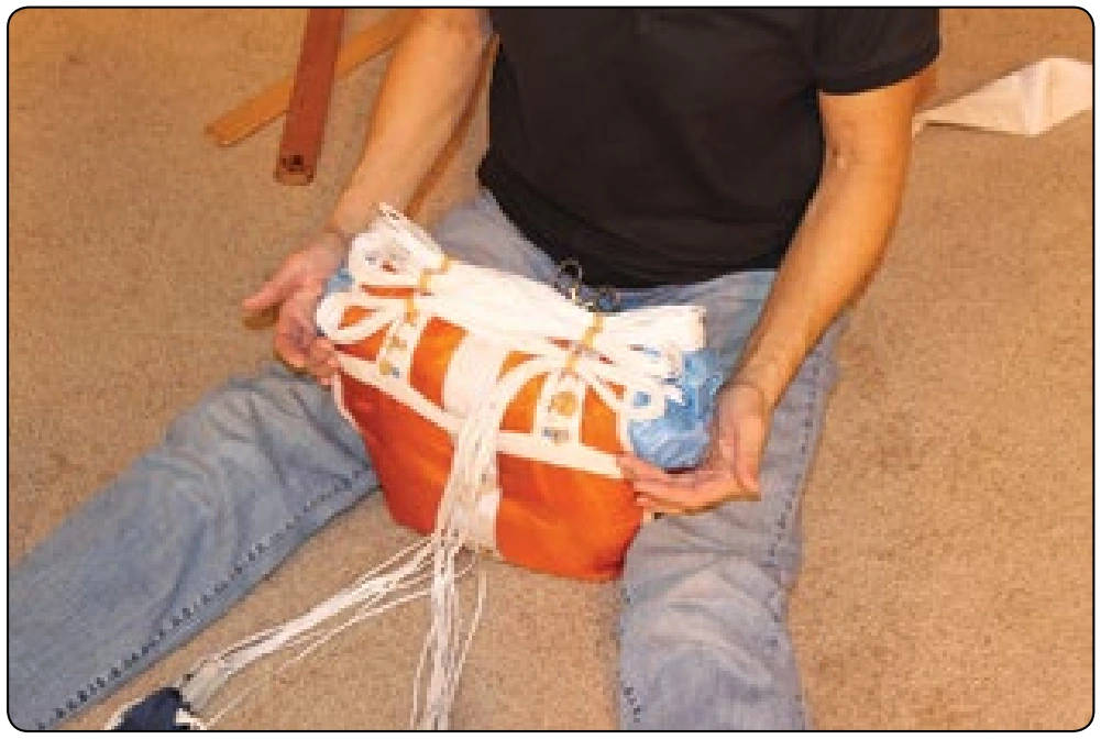
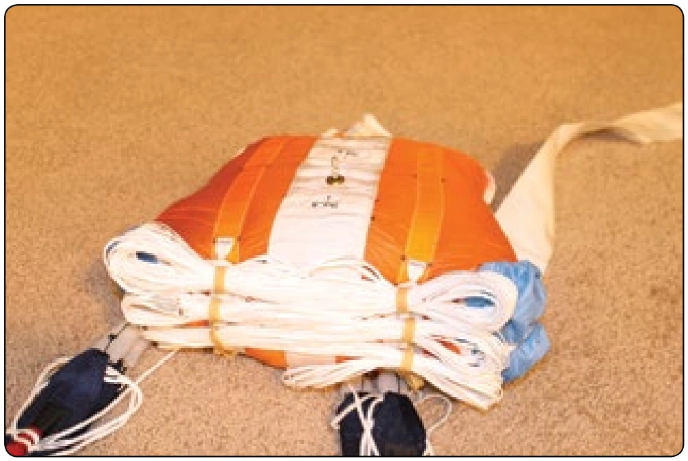
Figure 5-141. Depending on the length of the lines and the width of the bag, all of the rubber bands may or may not be used.
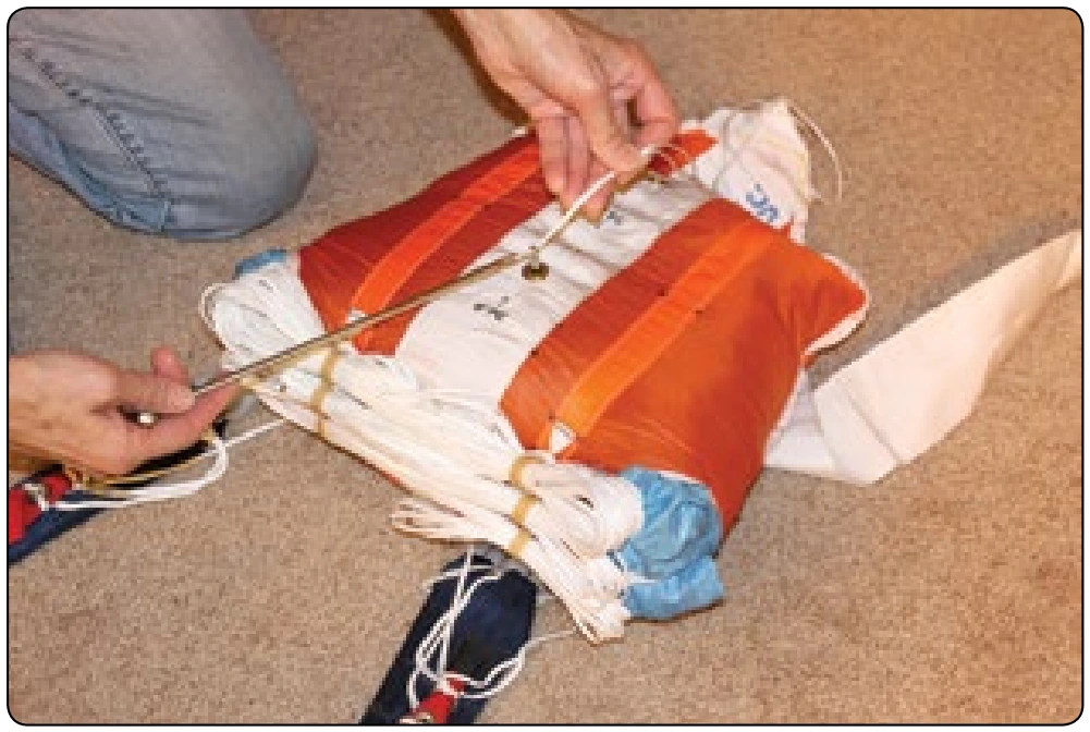
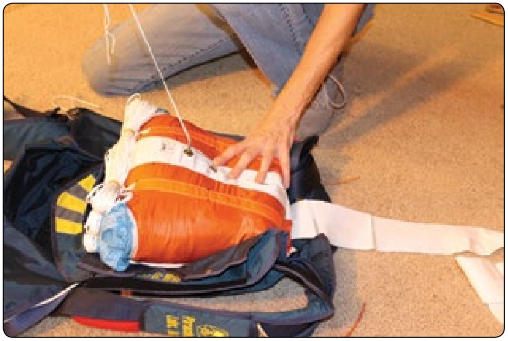
Figure 5-144. The second bodkin is now threaded through the bag in the opposite direction.
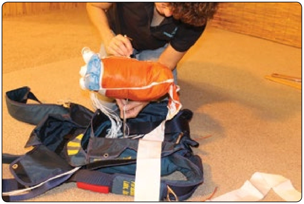
Figure 5-145. A bodkin that has been pre-loaded through the backpad of the container can now be easily pulled through the bag using this second bodkin.
Figure 5-142. Insert a bodkin through the channel in the bag where the hemostats were.
Figure 5-143. Pull a second bodkin through the bag using a pull up cord.
Figure 5-146. The bottom bodkin shown in place.