
Chapter 5
Inspection and Packing
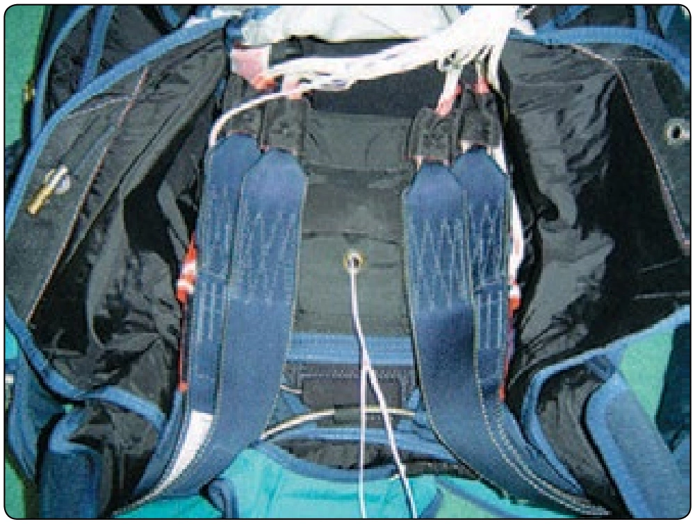
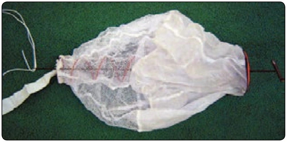
- Use the gun cleaning rod to thread the pull-up cord through the pilot chute. [Figure 5-108]
- Center the base of the pilot chute on the center grommet of the deployment bag.
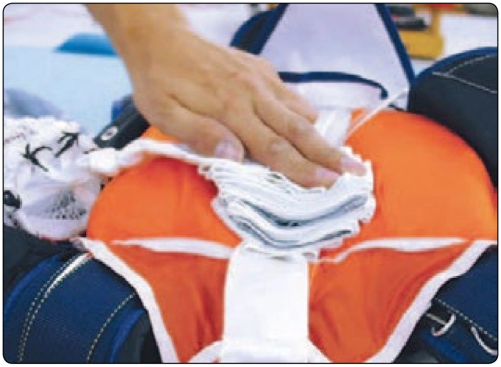
- Compress the pilot chute while stuffing fabric and mesh between the spring coils.
- Position the cap of the pilot chute with the arrow facing toward the top or bottom of the container. [Figure 5-109] Secure with a temporary pin.
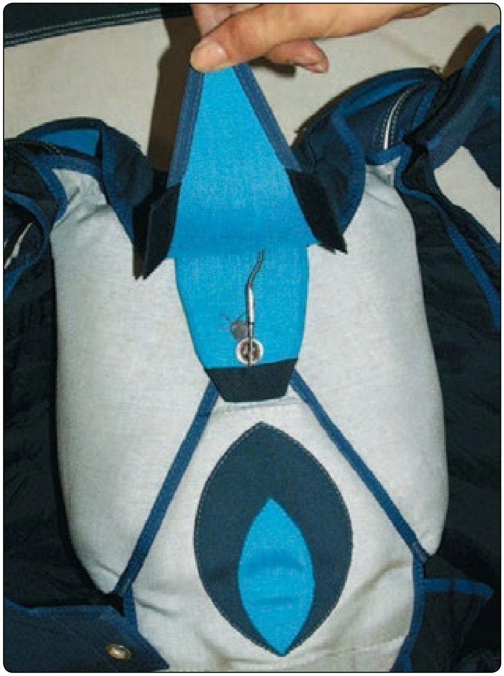
- If an AAD, such as a CYPRES®, is installed, route the pull-up cord through the cutter first, then through the right (#1) side flap grommet. [Figure 5-110]
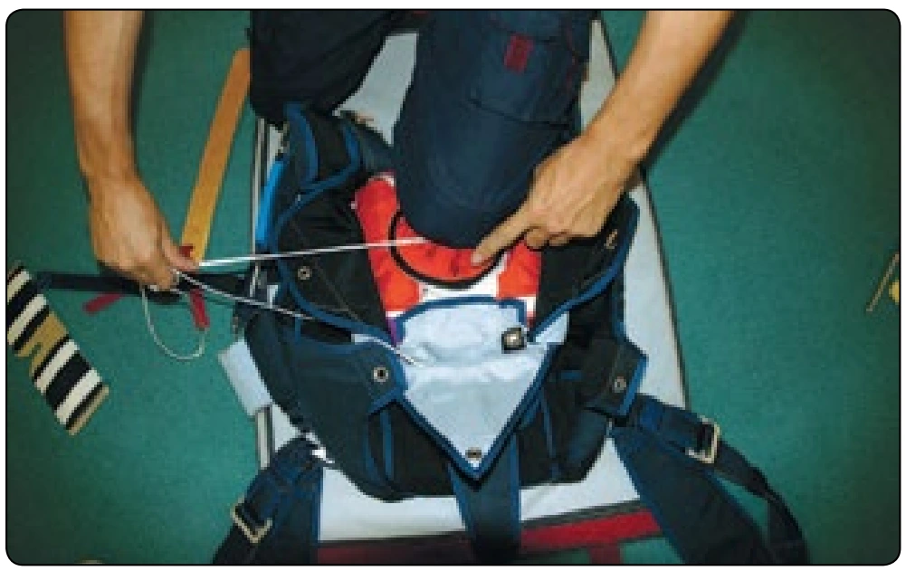
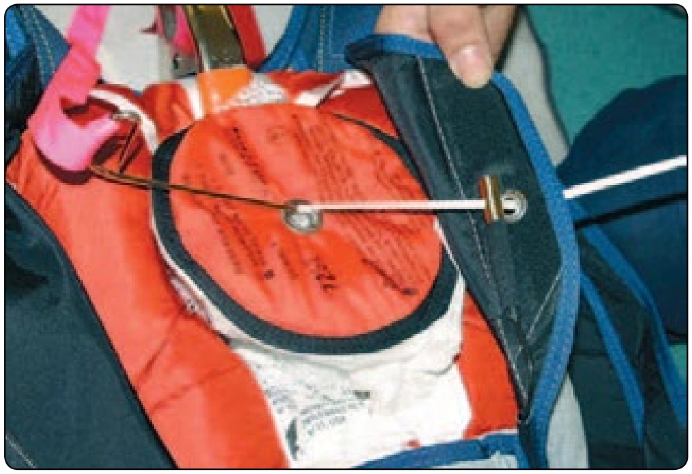
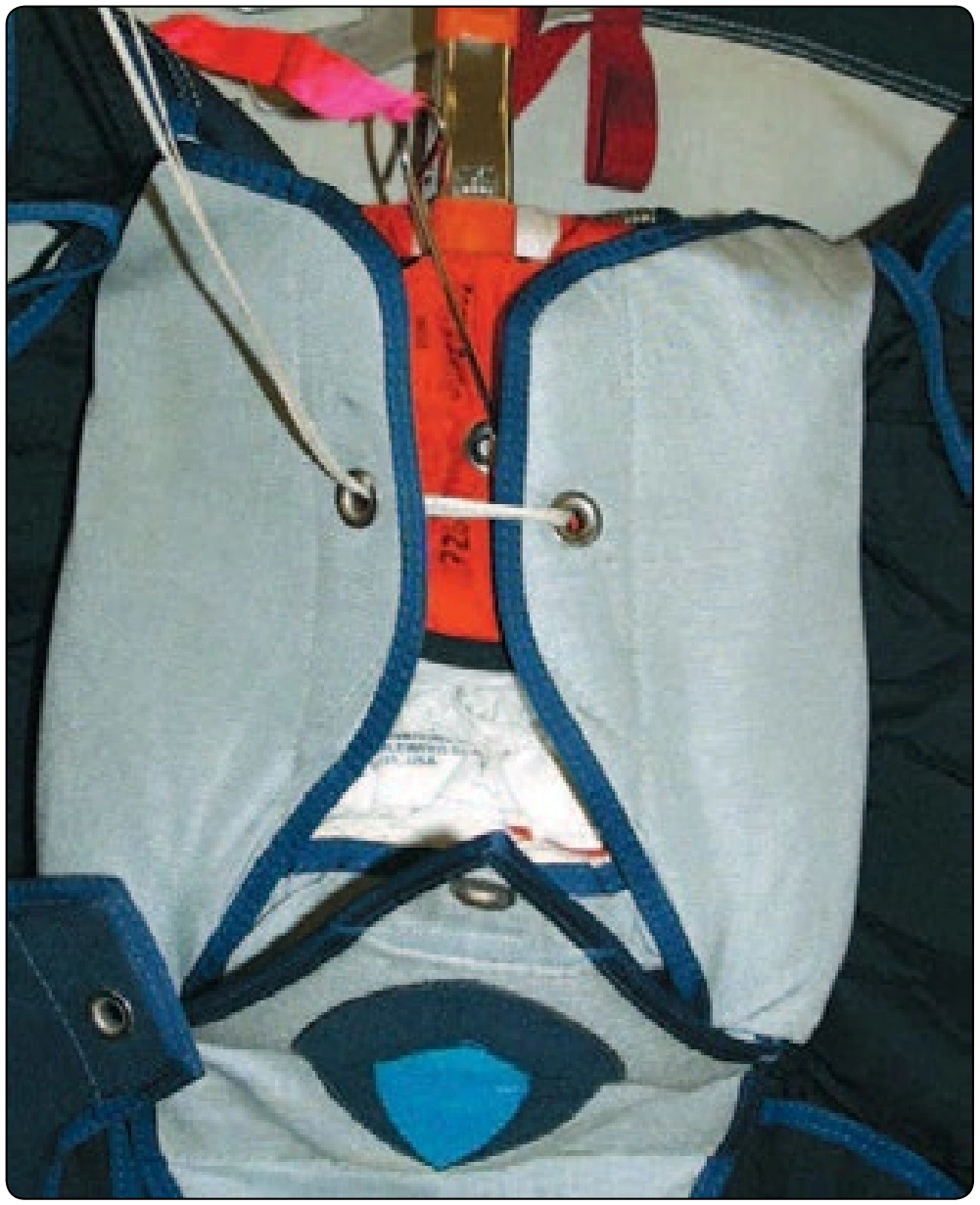
- Next thread the left (#2) side flap grommet. At the same time, close the side flaps. [Figure 5-111] Secure with a temporary pin.
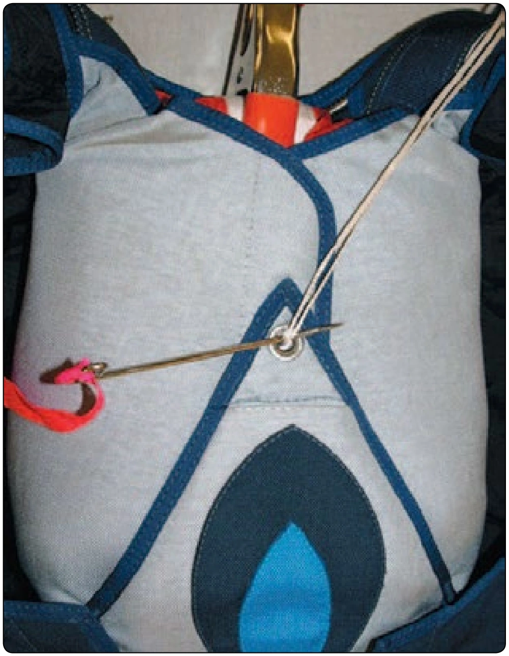
- Close the bottom flap (#3) and secure with a temporary pin. [Figure 5-112]
- Close flap #4 and insert the ripcord pin. [Figure 5-113]
- Once you are satisfied that the pull force is less than 22 pounds (10 kg), seal the ripcord and log the pack job.
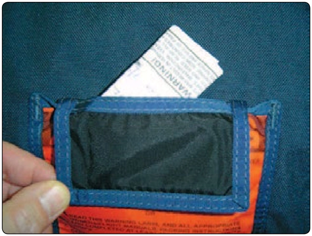
- Place the data card in the data card pocket. [Figure 5-114]
- Count your tools.
- Complete the placard data on the orange warning label. Failure to do so voids the TSO.
Ram-Air Reserve into a Two-Pin Piggyback
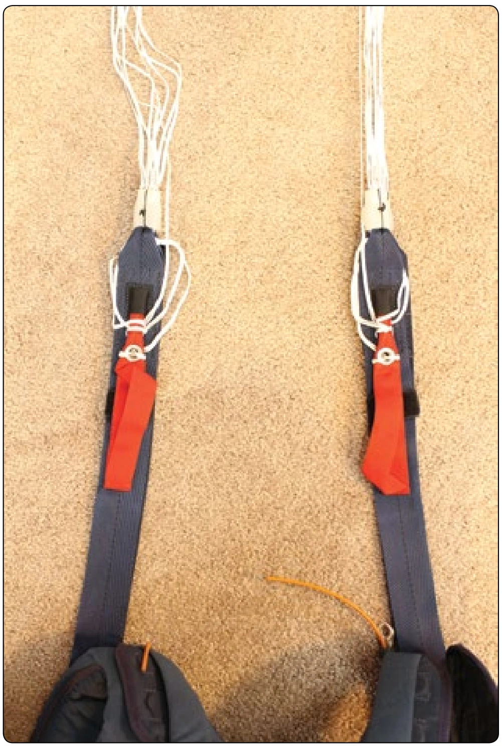
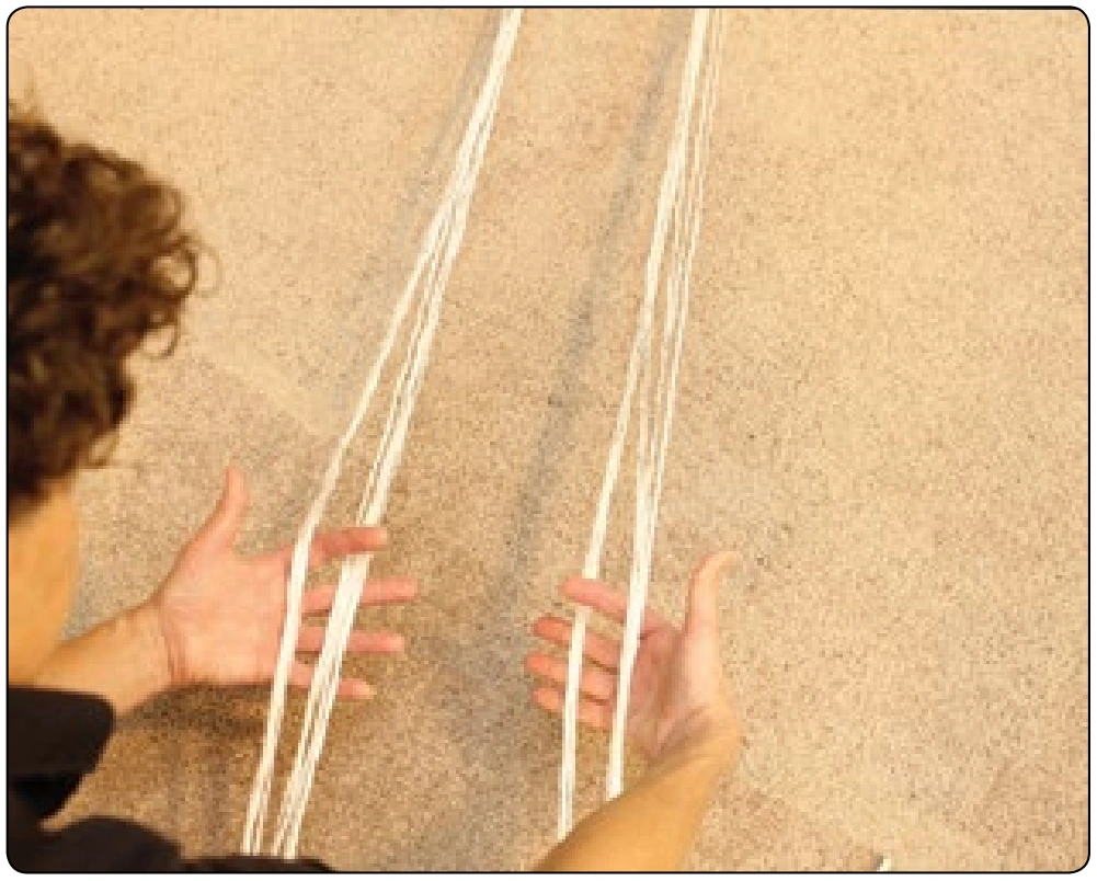
Many sport, military, and pilot emergency rigs feature the two pin, externally-mounted reserve pilot chute or Pop-Top. The Pop-Top closes use adjustable closing loops that are tightened after the pins are inserted. The following instructions demonstrate the PRO pack method without the use of clamps. [Figures 5-115 through 5-165]