Chapter 5
Inspection and Packing
The rigger must make sure to have the latest revision of the packing instructions, as well as any pertinent service bulletins from the manufacturer or Airworthiness Directives (AD) issued by the Federal Aviation Administration (FAA). The rigger may have a set of packing instructions that specifies a certain method for folding the canopy.
However, the manufacturer may have changed the method and issued a revision to the manual or a complete new one.
If the rigger is not completely sure that he or she has the latest information, then it is time to use the most valuable tool in their inventory—the telephone. A quick call to the manufacturer is all it takes to get the latest information. Most manufacturers publish their service bulletins in hard copy format and on their website.
In addition, the Parachute Industry Association (PIA) also has a listing of service bulletins at www.pia.com. It is most important that all riggers make an effort to maintain a comprehensive library of packing instructions and their associated service bulletins. Under Title 14 of the Code of Federal Regulations (14 CFR) part 65, section 65.129(e), the certificated rigger may not “pack, maintain, or alter a parachute in any manner that deviates from procedures approved by the Administrator or the manufacturer of the parachute.” In addition, 14 CFR part 65, section 65.129(f), also states that the certificated rigger may not “exercise the privileges of his certificate and type rating unless he understands the current manufacturer’s instructions for the operation involved.”
Component Compatibility
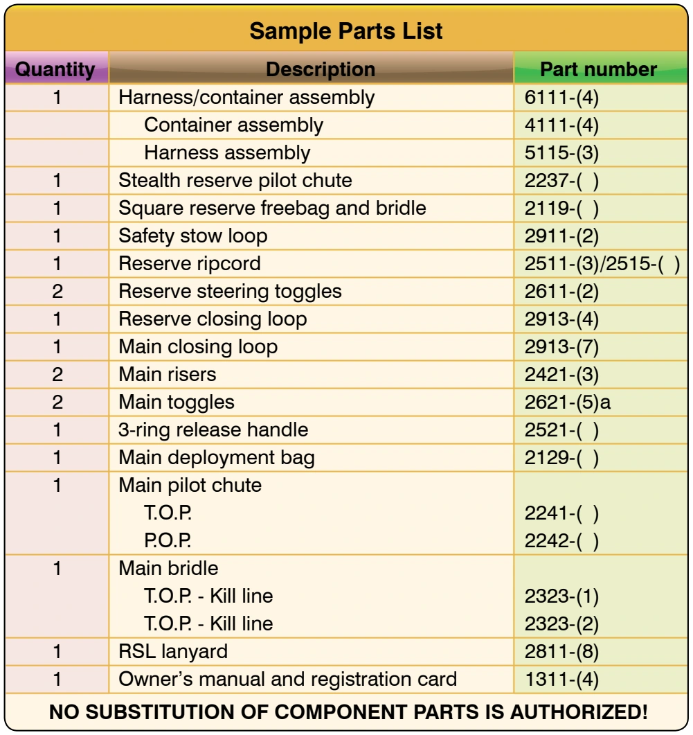
Once the rigger has all of the current manuals and information, the inspection can continue. This covers not just the canopy but also the entire assembly. In addition to looking for damage or contamination to the system, the rigger must make sure that all of the component parts are compatible and approved by the manufacturer. Figure 5-2 shows a sample parts list for a typical sport parachute, having dual parachutes in a single-harness system (a piggyback). This parts list delineates exactly what parts are used in the assembly of the system. The rigger should check each component part and its identifying label or stamp against the parts list. Mismatched component parts are among the most frequent problems found in the field. Many riggers are under the impression they can freely interchange component parts, but this may be done only within certain limits. Paragraph 11(a) of Advisory Circular (AC) 105-2, Sport Parachute Jumping, states: “The assembly or mating of approved parachute components from different manufacturers may be made by a certificated and appropriately-rated parachute rigger or parachute loft in accordance with the parachute manufacturer’s instructions and without further authorization by the manufacturer or the FAA. Specifically, when various parachute components are interchanged, the parachute rigger should follow the canopy manufacturer’s instructions, as well as the parachute container manufacturer’s instructions. However, the container manufacturer’s instructions take precedence when there is a conflict between the two.” In Figure 5-2, note the bold print at the bottom of the page: “NO SUBSTITUTION OF COMPONENT PARTS IS AUTHORIZED!” This manufacturer specifically states that you cannot use anything other than Original Equipment Manufacturer (OEM) parts. Substituting other parts places the rigger in violation of the Code of Federal Regulations (CFR).
A common problem found in the field concerns reserve ripcords. Several manufacturers of sport rigs use a one-pin ripcord with a mini trapezoidal handle and a cable length 27–29 inches long. Depending on the actual container it goes into, it is possible to use one manufacturer’s ripcord in another container as long as the rigger feels there is sufficient excess cable for safety reasons.
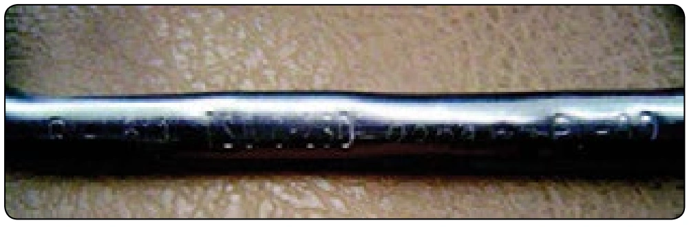
However, imagine one ripcord is 27 inches overall and is used in a system that is approved under Technical Standard Order (TSO) C-23b and is rated at 300 pounds. Another ripcord is 28 inches overall and is used in a system approved under TSO C-23c and is rated at 600 pounds for use with a Reserve Static Line (RSL) installation. The problem here is the mating of different TSO standard components. Installing the first ripcord in the second container with an RSL lanyard may be degrading the safety aspect of the system. So how does the rigger tell which is which? The ripcord approved under TSO C-23b has minimal markings, perhaps only a manufacturer’s part number. The ripcord approved under TSO C-23c has several markings on the handle as required by the TSO. It should have the manufacturer’s part number, manufacturer’s identification, TSO-C23c, and the batch or serial number or date of manufacture. [Figure 5-3] In reality, as long as the cable lengths are compatible, the function of the ripcord will probably work. The problem surfaces in the event of a problem or incident involving the system. At this point, the FAA could find the mismatched component and take action against the rigger who packed the parachute.
A bigger problem surfaces when the rigger substitutes a reserve deployment bag made by another manufacturer. Most reserve deployment bags are compatible with the appropriate container based on dimensions and volume. If the deployment bag does not fit correctly, there can be a problem with proper functioning of the system. These are two examples of the more common compatibility issues that are regularly found in the field. There are others that the rigger may encounter and need to address as well. The best solution is for the rigger to follow the manufacturer’s parts list strictly to ensure the safety of the parachute system.
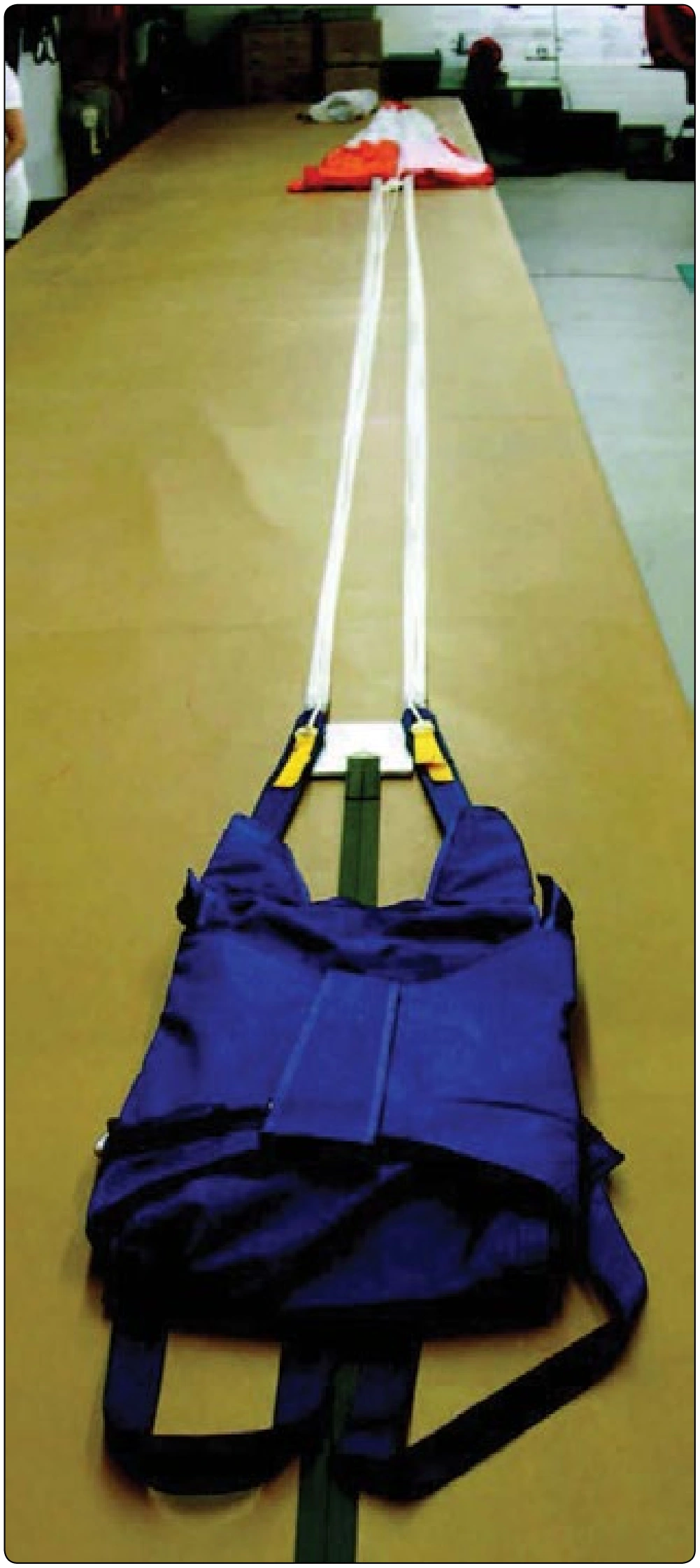
After the rigger has determined that all of the component parts are compatible, he or she can now commence the actual inspection of the parachute assembly. Figure 5-4 shows a typical pilot emergency parachute assembly with a round canopy laid out on the packing table. Make sure the canopy is straight and the apex lines are even. Then apply firm tension to the canopy and lines using a tension board. The standard is to start at the top of the assembly.
The assembly shown in Figure 5-4 can be broken down into the following six separate areas:
- Pilot chute and bridle
- Canopy and deployment device
- Suspension lines and connector links
- Container
- Harness including risers
- Ripcord
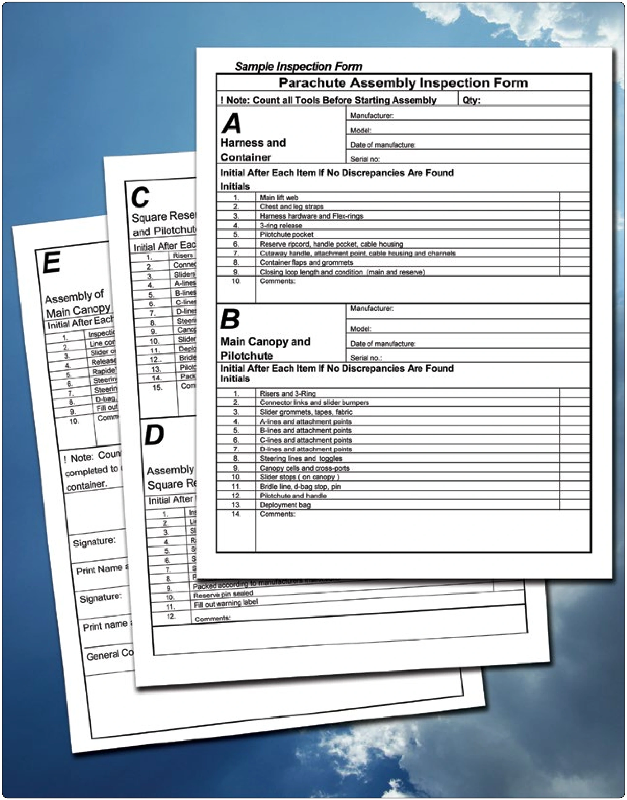
Inspection/packing checklists allow riggers to track their progress as they do their inspection. [Figure 5-5] It is desirable for riggers to complete their inspection uninterrupted, which ensures that the inspection process is followed and nothing gets overlooked. This rarely happens, however, due to normal interruptions, such as phone calls or customer questions. Using the inspection checklist ensures that after an interruption, the rigger is able to continue at the proper spot without missing anything. This checklist is divided into seven sections that make it usable for all types of parachute assemblies. It includes an area for counting the tools at the beginning and end of the inspection and packing procedure. This ensures that no tools are overlooked or left in the parachute. While this may sound implausible to some, it has happened over the years, sometimes with fatal consequences.
Round Canopies and Pilot Emergency Systems
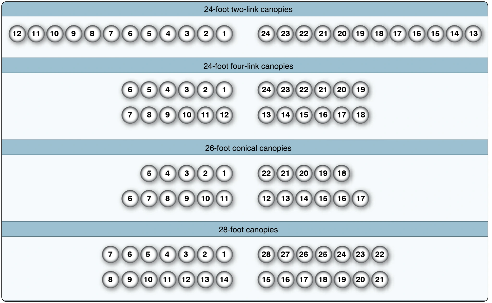
The first thing the rigger should check is the continuity of the canopy to make sure it is straight. Do so by laying the system on the table as if the wearer were laying face down, head toward the canopy. (On some models, such as military seat parachutes, it may be face down with the feet towards the canopy.) Make sure to follow the manufacturer’s instructions. Ensure that the canopy is right side out (i.e., the data panel faces out) and the gore numbers are readable on the outside. Attach the required tension devices and apply light tension. Standing at the canopy, split the riser line groups and grasp the two gores that separate them. The top panel should have line number 1 and the last line of the sequence depending on the number of lines on the canopy. Starting with number 1, the lines will run in sequence counterclockwise around the canopy. [Figure 5-6] The four lines attached to these two gores comprise the standard “four-line check” for a round canopy. By running these four lines from the canopy to the connector links, the rigger can make a quick check of straightness. If the rigger was the last person to pack the parachute, he or she may feel this is sufficient to ensure continuity. However, most riggers do a full check of all the lines, even on their own pack jobs.