
Chapter 2
Aerodynamics of Flight
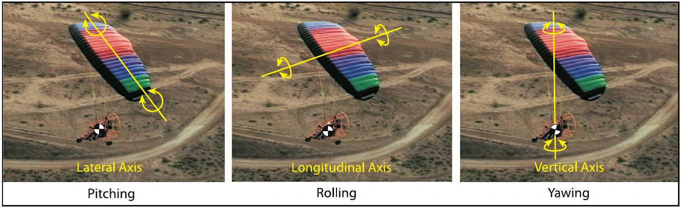
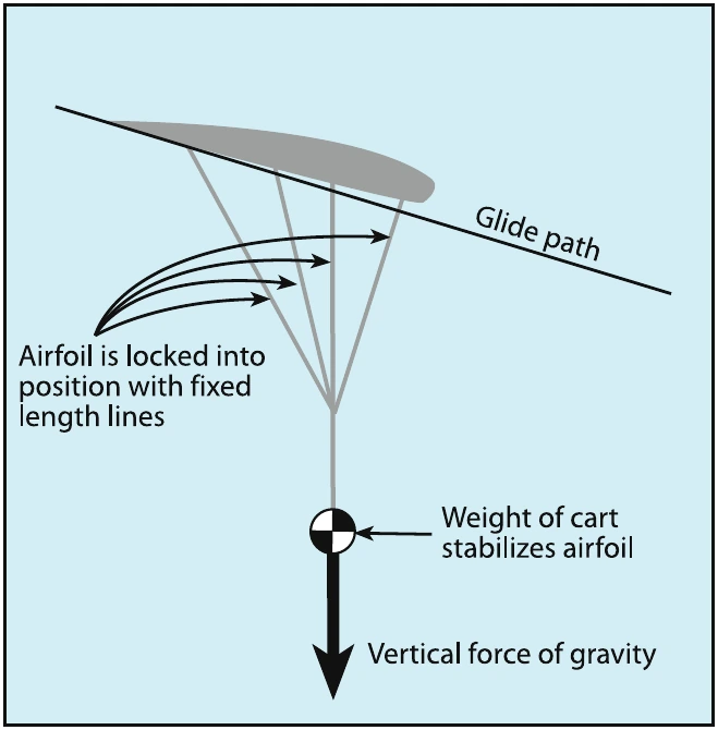
The “dynamic pendulum effect” can be demonstrated by swinging the weight around and then stopping the swinging to notice that the weight keeps swinging from the momentum. The swinging weight is known as the “dynamic pendulum effect” which will be discussed in detail later.
Thrust Line Moments
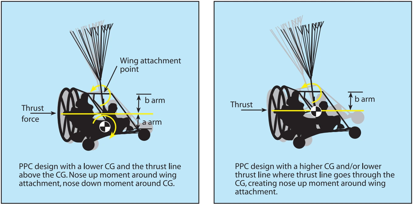
PPC designs can have different moments caused by thrust; the propeller thrust may be above the CG (Figure 2-21 left) or go through the CG (Figure 2-21 right). Since the cart swings free in pitch, this CG thrust moment can slightly affect the pitch of the cart in relation to the wing.
PPCs with an attachment point above the thrust line have a pitching nose up moment as shown in Figure 2-21 (both diagrams), with a thrust line, wing attach point, and arm “b.”
Gravity Moment
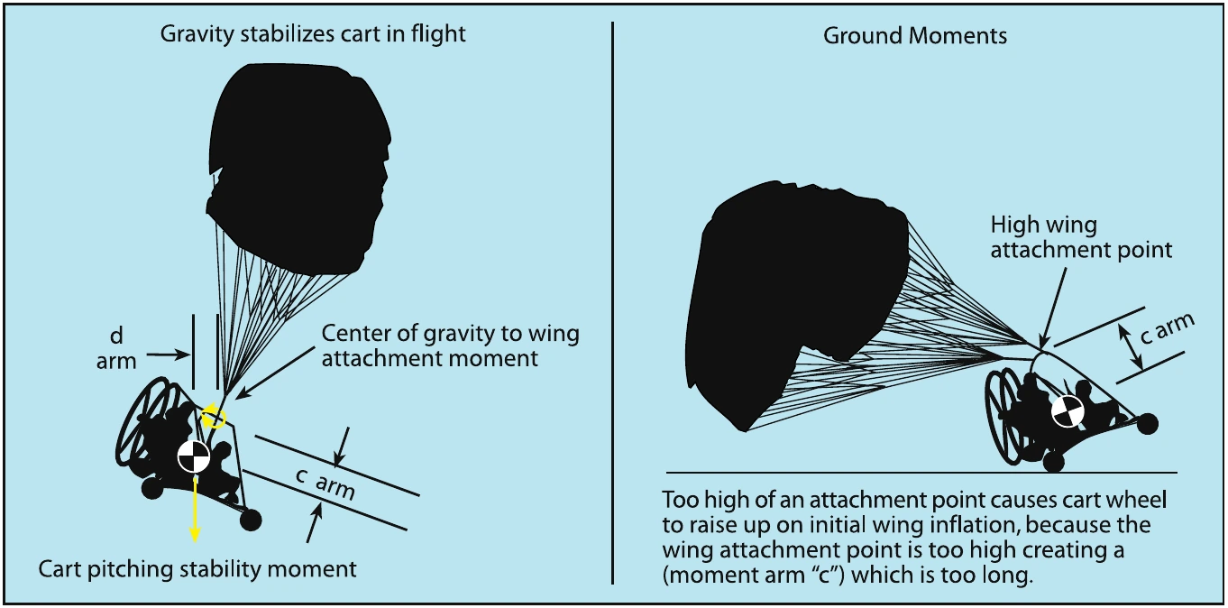
There is a moment arm from the CG of the cart, to the cart/wing attachment (see “arms” in Figure 2-22). The longer the distance from the CG to the wing attachment point, the more stable the cart pitch is from thrust moments. The higher the wing attachment point above the CG, the more stable the cart is from swinging underneath and the less the cart will pitch up when thrust is applied.
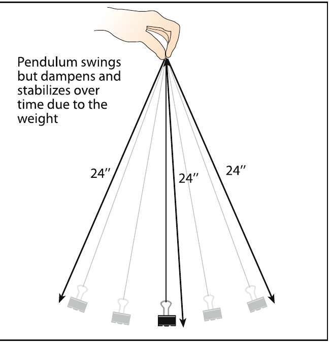
A higher hang point will also better stabilize the PPC cart in turbulence because the moment of the weight and the larger “d” arm creates a larger stabilizing moment. [Figure 2-22]
For ground operations, the moment arm distance “c” cannot be too great or the front wheel would lift off the ground prematurely, trying to inflate the wing (see right side of Figure 2-22).
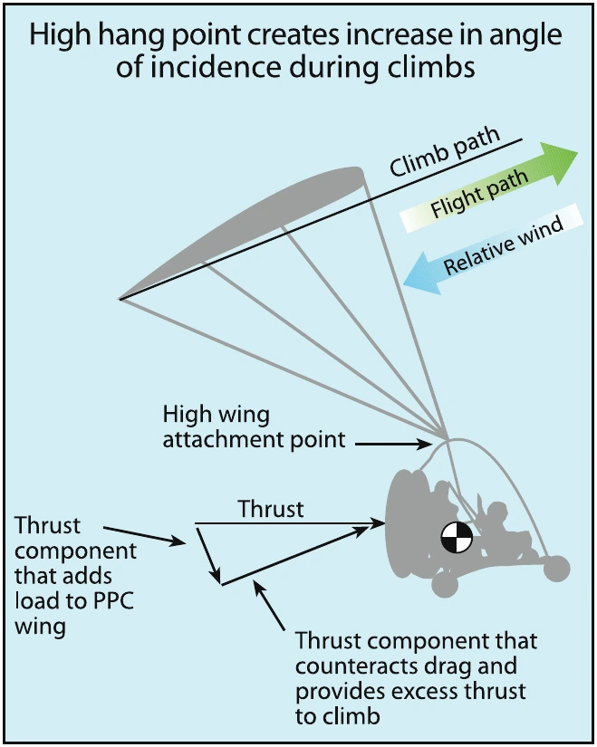
During flight, the advantage of a high attachment point arm “c” is less swinging around of the cart under the wing, and less cart “pitch up” when throttle is applied to climb. This high attachment point creates thrust that is now pointed slightly down to the relative wind, which has two significant effects. First, it creates a negative P-factor, counteracting increased torque. The second effect is a disadvantage: less climb rate or more thrust required for the same climb rate. This is due to the increased load on the wing from the thrust, requiring more speed and/or angle of attack to lift the total load. [Figure 2-23]
Wing Attachment to Cart
If flying straight and level over a perfectly flat landing strip, then with the rear wheels 1 inch above the runway, the nose wheel should be between 7 and 11 inches above the pavement. The POH specifies the wing fore and aft wing attachment points to the cart. [Figure 2-24] Attaching the wing too far forward would cause the nose wheel to be higher than it should. Attaching the wing too far back would place the nose wheel too low, where it would hit first for landings. Balancing the cart properly per the POH is important to make sure the cart is hanging properly under the wing and ensure thrust is properly aligned as designed by the manufacturer. Nose wheel low means thrust pointing down, increasing loads, and airspeed. Nose wheel high has the opposite effect. Thrust aligned too high or too low results in reduced thrust and unwanted P-factor.
Manufacturers must balance the cart stability for takeoff and flight, along with the thrust moment to achieve the best design for the specific application.
Stability
A stable aircraft is one that will routinely return to its original attitude after it has been disturbed from this condition; usually this means returning to straight-and-level flight after encountering turbulence that disrupts a normal flightpath. The more stable the aircraft, the easier it is to return to a straight and level position. The natural tendency of the pendulum — the PPC cart hanging under the wing — is to return to its original centered position under the wing. The pendulum design gives the PPC airborne positive dynamic stability and positive static stability for roll and pitch because the weight of the pendulum wants to return the PPC to level stabilized flight. No matter what maneuver within the POH limitations the PPC is put through (regardless of whether it is pilot induced or turbulence created), as soon as the disruptive force stops, the aircraft is designed to return to a stabilized flight condition, with virtually no pilot input. Figure 2-25 shows the movements of the PPC as it auto-corrects from a side gust of wind.