Chapter 12
Attitude Instrument Flying
Cross-check the ball of the turn-and-slip indicator to determine that the helicopter is in coordinated flight. If the rotor is laterally level and torque is properly compensated for by pedal pressure, the ball remains in the center. To center the ball, level the helicopter laterally by reference to the other bank instruments, then center the ball with pedal trim. Torque correction pressures vary as you make power changes. Always check the ball following such changes.
Common Errors During Straight-and-Level Flight
- Failure to maintain altitude.
- Failure to maintain heading.
- Overcontrolling pitch and bank during corrections.
- Failure to maintain proper pedal trim.
- Failure to cross-check all available instruments.
Power Control During Straight-and-Level Flight
Establishing specific power settings is accomplished through collective pitch adjustments and throttle control, where necessary. For reciprocating powered helicopters, power indications are observed on the manifold pressure gauge. For turbine powered helicopters, power is observed on the torque gauge. (Since most IFR certified helicopters are turbine powered, this discussion concentrates on this type of helicopter.)
At any given airspeed, a specific power setting determines whether the helicopter is in level flight, in a climb, or in a descent. For example, cruising airspeed maintained with cruising power results in level flight.
If you increase the power setting and hold the airspeed constant, the helicopter climbs. Conversely, if you decrease power and hold the airspeed constant, the helicopter descends. As a rule of thumb, in a turbine-engine powered helicopter, a 10 to 15 percent change in the torque value required to maintain level flight results in a climb or descent of approximately 500 f.p.m., if the airspeed remains the same.
If the altitude is held constant, power determines the airspeed. For example, at a constant altitude, cruising power results in cruising airspeed. Any deviation from the cruising power setting results in a change of airspeed. When power is added to increase airspeed, the nose of the helicopter pitches up and yaws to the right in a helicopter with a counterclockwise main rotor blade rotation. When power is reduced to decrease airspeed, the nose pitches down and yaws to the left. The yawing effect is most pronounced in single-rotor helicopters, and is absent in helicopters with counter-rotating rotors. To counteract the yawing tendency of the helicopter, apply pedal trim during power changes.
To maintain a constant altitude and airspeed in level flight, coordinate pitch attitude and power control. The relationship between altitude and airspeed determines the need for a change in power and/or pitch attitude. If the altitude is constant and the airspeed is high or low, change the power to obtain the desired airspeed.
During the change in power, make an accurate interpretation of the altimeter; then counteract any deviation from the desired altitude by an appropriate change of pitch attitude. If the altitude is low and the airspeed is high, or vice versa, a change in pitch attitude alone may return the helicopter to the proper altitude and airspeed. If both airspeed and altitude are low, or if both are high, a change in both power and pitch attitude is necessary.
To make power control easy when changing airspeed, it is necessary to know the approximate power settings for the various airspeeds that will be flown. When the airspeed is to be changed any appreciable amount, adjust the torque so that it is approximately five percent over or under that setting necessary to maintain the new airspeed.
As the power approaches the desired setting, include the torque meter in the cross-check to determine when the proper adjustment has been accomplished. As the airspeed is changing, adjust the pitch attitude to maintain a constant altitude. A constant heading should be maintained throughout the change. As the desired airspeed is approached, adjust power to the new cruising power setting and further adjust pitch attitude to maintain altitude.
Overpowering and underpowering torque approximately five percent results in a change of airspeed at a moderate rate, which allows ample time to adjust pitch and bank smoothly. The instrument indications for straight-and-level flight at normal cruise, and during the transition from normal cruise to slow cruise are illustrated in figures 12-15 and 12-16 on the next page. After the airspeed has stabilized at slow cruise, the attitude indicator shows an approximate level pitch attitude.
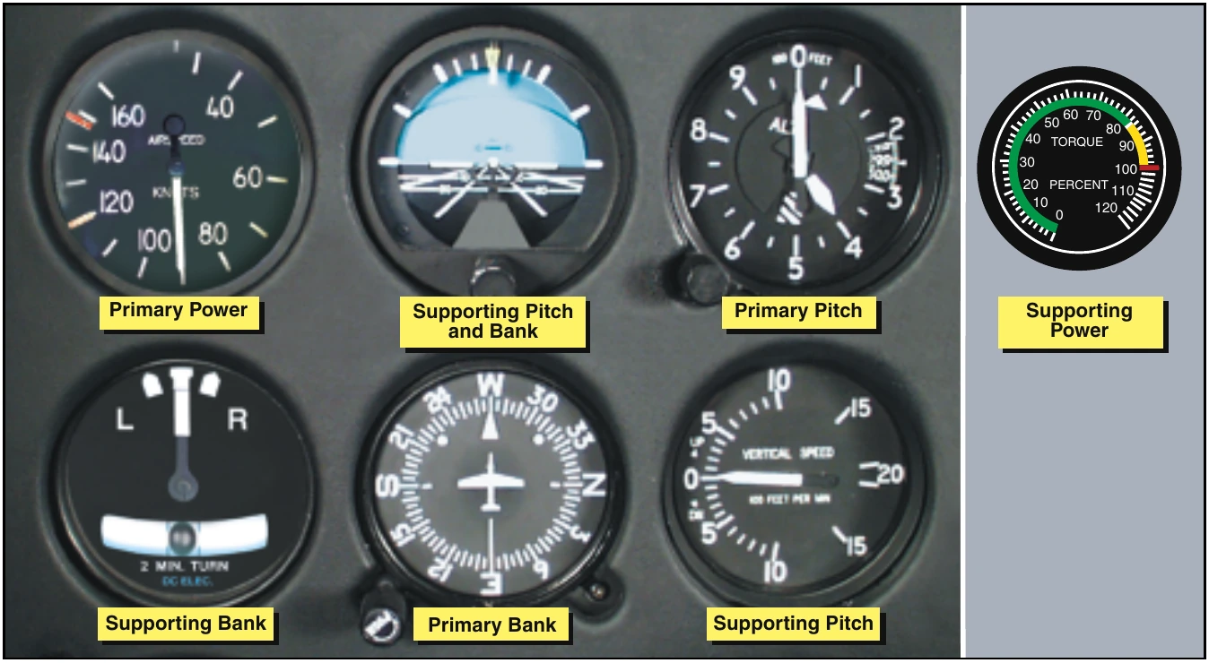
The altimeter is the primary pitch instrument during level flight, whether flying at a constant airspeed, or during a change in airspeed. Altitude should not change during airspeed transitions. The heading indicator remains the primary bank instrument. Whenever the airspeed is changed any appreciable amount, the torque meter is momentarily the primary instrument for power control. When the airspeed approaches that desired, the airspeed indicator again becomes the primary instrument for power control.
The cross-check of the pitch and bank instruments to produce straight-and-level flight should be combined with the power control instruments. With a constant power setting, a normal cross-check should be satisfactory. When changing power, the speed of the cross-check must be increased to cover the pitch and bank instruments adequately. This is necessary to counteract any deviations immediately.
Common Errors During Airspeed Changes
- Improper use of power.
- Overcontrolling pitch attitude.
- Failure to maintain heading.
- Failure to maintain altitude.
- Improper pedal trim.
Straight Climbs (Constant Airspeed and Constant Rate)
For any power setting and load condition, there is only one airspeed that will give the most efficient rate of climb. To determine this, you should consult the climb data for the type of helicopter being flown. The technique varies according to the airspeed on entry and whether you want to make a constant airspeed or constant rate climb.