
Chapter 3
Aerodynamics of Flight
Pendular Action
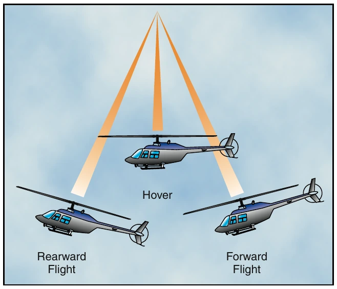
Since the fuselage of the helicopter, with a single main rotor, is suspended from a single point and has considerable mass, it is free to oscillate either longitudinally or laterally in the same way as a pendulum. This pendular action can be exaggerated by over controlling; therefore, control movements should be smooth and not exaggerated. [Figure 3-3]
Coning
In order for a helicopter to generate lift, the rotor blades must be turning. This creates a relative wind that is opposite the direction of rotor system rotation. The rotation of the rotor system creates centrifugal force (inertia), which tends to pull the blades straight outward from the main rotor hub. The faster the rotation, the greater the centrifugal force. This force gives the rotor blades their rigidity and, in turn, the strength to support the weight of the helicopter. The centrifugal force generated determines the maximum operating rotor r.p.m. due to structural limitations on the main rotor system.
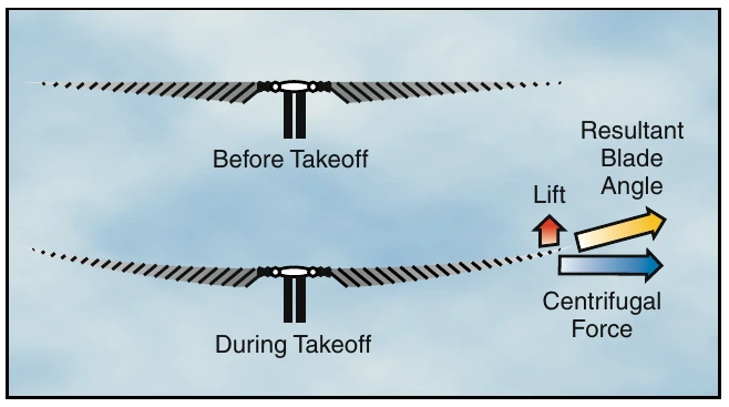
As a vertical takeoff is made, two major forces are acting at the same time—centrifugal force acting outward and perpendicular to the rotor mast, and lift acting upward and parallel to the mast. The result of these two forces is that the blades assume a conical path instead of remaining in the plane perpendicular to the mast. [Figure 3-4]
Coriolis Effect (Law of Conservation of Angular Momentum)
Coriolis Effect, which is sometimes referred to as conservation of angular momentum, might be compared to spinning skaters. When they extend their arms, their rotation slows down because the center of mass moves farther from the axis of rotation. When their arms are retracted, the rotation speeds up because the center of mass moves closer to the axis of rotation.
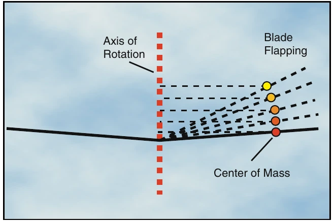
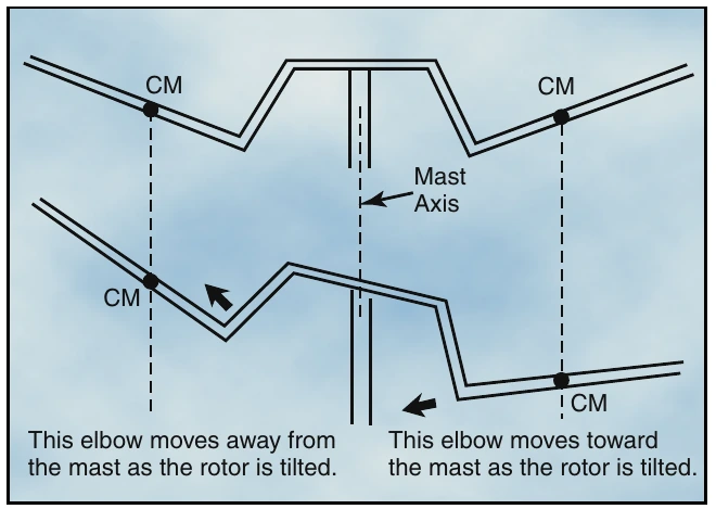
When a rotor blade flaps upward, the center of mass of that blade moves closer to the axis of rotation and blade acceleration takes place in order to conserve angular momentum. Conversely, when that blade flaps downward, its center of mass moves further from the axis of rotation and blade deceleration takes place. [Figure 3-5] Keep in mind that due to coning, a rotor blade will not flap below a plane passing through the rotor hub and perpendicular to the axis of rotation. The acceleration and deceleration actions of the rotor blades are absorbed by either dampers or the blade structure itself, depending upon the design of the rotor system.
Centrifugal Force— The apparent force that an object moving along a circular path exerts on the body constraining the obect and that acts outwardy away from the center of rotation.
Two-bladed rotor systems are normally subject to Coriolis Effect to a much lesser degree than are articulated rotor systems since the blades are generally “underslung” with respect to the rotor hub, and the change in the distance of the center of mass from the axis of rotation is small. [Figure 3-6] The hunting action is absorbed by the blades through bending. If a two-bladed rotor system is not “underslung,” it will be subject to Coriolis Effect comparable to that of a fully articulated system.
Ground Effect
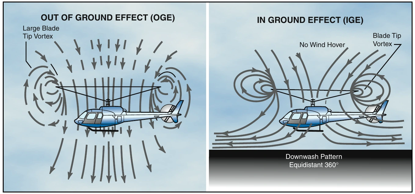
When hovering near the ground, a phenomenon known as ground effect takes place. [Figure 3-7] This effect usually occurs less than one rotor diameter above the surface. As the induced airflow through the rotor disc is reduced by the surface friction, the lift vector increases.
This allows a lower rotor blade angle for the same amount of lift, which reduces induced drag. Ground effect also restricts the generation of blade tip vortices due to the downward and outward airflow making a larger portion of the blade produce lift. When the helicopter gains altitude vertically, with no forward airspeed, induced airflow is no longer restricted, and the blade tip vortices increase with the decrease in outward airflow. As a result, drag increases which means a I I /higher pitch angle, and more power is needed to move the air down through the rotor.
Ground effect is at its maximum in a no-wind condition over a firm, smooth surface. Tall grass, rough terrain, revetments, and water surfaces alter the airflow pattern, causing an increase in rotor tip vortices.