
Chapter 3
Aerodynamics of Flight
Gyroscopic Precession
The spinning main rotor of a helicopter acts like a gyroscope. As such, it has the properties of gyroscopic action, one of which is precession. Gyroscopic precession is the resultant action or deflection of a spinning object when a force is applied to this object. This action occurs approximately 90° in the direction of rotation from the point where the force is applied. [Figure 3-8]
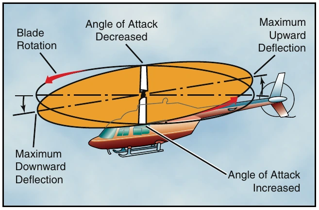
Let us look at a two-bladed rotor system to see how gyroscopic precession affects the movement of the tip-path plane. Moving the cyclic pitch control increases the angle of attack of one rotor blade with the result that a greater lifting force is applied at that point in the plane of rotation. This same control movement simultaneously decreases the angle of attack of the other blade the same amount, thus decreasing the lifting force applied at that point in the plane of rotation. The blade with the increased angle of attack tends to flap up; the blade with the decreased angle of attack tends to flap down. Because the rotor disk acts like a gyro, the blades reach maximum deflection at a point approximately 90° later in the plane of rotation. As shown in figure 3-9, the retreating blade angle of attack is increased and the advancing blade angle of attack is decreased resulting in a tipping forward of the tip-path plane, since maximum deflection takes place 90° later when the blades are at the rear and front, respectively.
In a rotor system using three or more blades, the movement of the cyclic pitch control changes the angle of attack of each blade an appropriate amount so that the end result is the same.
Vertical Flight
Hovering is actually an element of vertical flight.
Increasing the angle of attack of the rotor blades (pitch) while their velocity remains constant generates additional vertical lift and thrust and the helicopter ascends.
Decreasing the pitch causes the helicopter to descend.
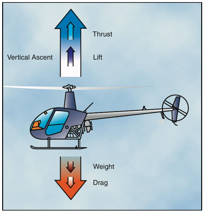
In a no wind condition when lift and thrust are less than weight and drag, the helicopter descends vertically. If lift and thrust are greater than weight and drag, the helicopter ascends vertically. [Figure 3-10]
Forward Flight
In or during forward flight, the tip-path plane is tilted forward, thus tilting the total lift-thrust force forward from the vertical. This resultant lift-thrust force can be resolved into two components—lift acting vertically upward and thrust acting horizontally in the direction of flight. In addition to lift and thrust, there is weight (the downward acting force) and drag (the rearward acting or retarding force of inertia and wind resistance). [Figure 3-11]
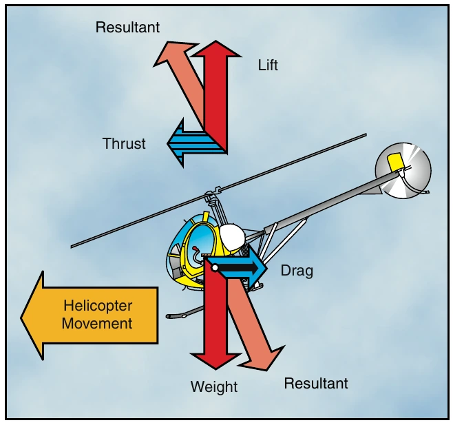
In straight-and-level, unaccelerated forward flight, lift equals weight and thrust equals drag (straight-and-level flight is flight with a constant heading and at a constant altitude). If lift exceeds weight, the helicopter climbs; if lift is less than weight, the helicopter descends. If thrust exceeds drag, the helicopter speeds up; if thrust is less than drag, it slows down.
As the helicopter moves forward, it begins to lose altitude because of the lift that is lost as thrust is diverted forward. However, as the helicopter begins to accelerate, the rotor system becomes more efficient due to the increased airflow. The result is excess power over that which is required to hover. Continued acceleration causes an even larger increase in airflow through the rotor disc and more excess power.
Translational Lift
Translational lift is present with any horizontal flow of air across the rotor. This increased flow is most noticeable when the airspeed reaches approximately 16 to 24 knots. As the helicopter accelerates through this speed, the rotor moves out of its vortices and is in relatively undisturbed air. The airflow is also now more horizontal, which reduces induced flow and drag with a corresponding increase in angle of attack and lift. The additional lift available at this speed is referred to as “effective translational lift” (ETL). [Figure 3-12]
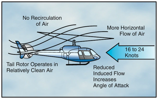
When a single-rotor helicopter flies through translational lift, the air flowing through the main rotor and over the tail rotor becomes less turbulent and more aerodynamically efficient. As the tail rotor efficiency improves, more thrust is produced causing the aircraft to yaw left in a counterclockwise rotor system. It will be necessary to use right torque pedal to correct for this tendency on takeoff. Also, if no corrections are made, the nose rises or pitches up, and rolls to the right. This is caused by combined effects of dissymmetry of lift and transverse flow effect, and is corrected with cyclic control.