Searchable explanations of IFR enroute airports, radio aids, airspace, airways, foreign areas, and terrain contours.
LF/MF airwaysairways based on LF/MF NAVAIDsare sometimes called "colored airways" because they are identified by color name and number (e.g., "Amber One", charted as "A1"). In Alaska, Green and Red airways are plotted east and west, and Amber and Blue airways are plotted north and south. Regardless of their color identifier, LF/MF airways are shown in brown.
Users need to be aware that a NOTAM addressing activation will NOT be issued to announce permanently listed times of use. High and Low Low Altitude Only P - Prohibited Area MOA - Military Operations Area R - Restricted Area A - Alert Area * W - Warning Area * Alert Areas do not extend into Class A, B, C and D airspace, or Class E airport surface areas. See Airspace Tabulation on chart for complete information. OTHER AIRSPACE FAR 91 Special Air Traffic Rules are shown with the type NO SVFR above the airport name. FAR 93 Special Airspace Traffic Rules are shown with a solid line box around the airport name, indicating FAR 93 Special Requirements see Chart Supplement. Mode C Required Airspace (from the surface to 10,000' MSL) within 30 NM radius of the primary airport(s) for which a Class B airspace is designated, is depicted on IFR Enroute Low Altitude Charts as a blue circle labeled MODE C & ADS-B OUT 30 NM. MODE C & ADS-B OUT 30 NM Mode C & ADS-B Out is also required for operations within and above all Class C airspace up to 10,000' MSL, but not depicted. See FAR 91.215 and the AIM. INSTRUMENT AIRWAYS The FAA has established two fixed route systems for air navigation. The VOR and LF/MF system-designated from 1,200' Above Ground Level (AGL) to but not including FL 180 is shown on IFR Enroute Low Altitude Charts, and the Jet Route system designated from FL 180 to FL 450 inclusive is shown on IFR Enroute High Altitude Charts. VOR LF/MF AIRWAY SYSTEM (IFR LOW ALTITUDE ENROUTE CHARTS) In this system VOR airwaysairways based on VOR or VORTAC NAVAIDsare depicted in black and identified by a "V" (Victor) followed by the route number (e.g., "V12"). LF/MF airwaysairways based on LF/MF NAVAIDsare sometimes called "colored airways" because they are identified by color name and number (e.g., "Amber One", charted as "A1"). In Alaska, Green and Red airways are plotted east and west, and Amber and Blue airways are plotted north and south. Regardless of their color identifier, LF/MF airways are shown in brown.
Source page 69
AIRWAY/ROUTE DATA
On both series of IFR Enroute Charts, airway/route data such as the airway identifications, magnetic courses bearings or radials, mileages, and altitudes (e.g., Minimum Enroute Altitudes (MEAs), Minimum Reception Altitudes (MRAs), Maximum Authorized Altitudes (MAAs), Minimum Obstacle Clearance Altitudes (MOCAs), Minimum Turning Altitudes (MTAs) and Minimum Crossing Altitudes (MCAs)) are shown aligned with the airway.
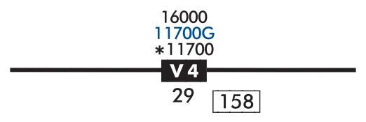
As a rule the airway/route data is charted and in the same color as the airway, with one exception. Charted in blue, Global Navigation Satellite System (GNSS) MEAs, identified with a "G" suffix, have been added to "V" and "colored airways" for aircraft flying those airways using Global Positioning System (GPS) navigation.
Airways/Routes predicated on VOR or VORTAC NAVAIDs are defined by the outbound radial from the NAVAID. Airways/Routes predicated on LF/MF NAVAIDs are defined by the inbound bearing.
Minimum Enroute Altitude (MEA)
The MEA is the lowest published altitude between radio fixes that assures acceptable navigational signal coverage and meets obstacle clearance requirements between those fixes. The MEA prescribed for a Federal airway or segment, RNAV low or high route, or other direct route applies to the entire width of the airway, segment, or route between the radio fixes defining the airway, segment, or route. MEAs for routes wholly contained within controlled airspace normally provide a buffer above the floor of controlled airspace consisting of at least 300 feet within transition areas and 500 feet within control areas. MEAs are established based upon obstacle clearance over terrain and man-made objects, adequacy of navigation facility performance, and communications requirements.
Minimum Reception Altitude (MRA)
MRAs are determined by FAA flight inspection traversing an entire route of flight to establish the minimum altitude the navigation signal can be received for the route and for off-course NAVAID facilities that determine a fix. When the MRA at the fix is higher than the MEA, an MRA is established for the fix and is the lowest altitude at which an intersection can be determined.
Maximum Authorized Altitude (MAA)
An MAA is a published altitude representing the maximum usable altitude or flight level for an airspace structure or route segment. It is the highest altitude on a Federal airway, jet route, RNAV low or high route, or other direct route for which an MEA is designated at which adequate reception of navigation signals is assured.
Minimum Obstruction Clearance Altitude (MOCA)
The MOCA is the lowest published altitude in effect between radio fixes on VOR airways, off-airway routes, or route segments that meets obstacle clearance requirements for the entire route segment and assures acceptable navigational signal coverage only within 25 statute (22 nautical) miles of a VOR. A MOCA is only shown on the Enroute Low Charts and only published when it is lower than the MEA. When shown, it is preceded by an asterisk.
Minimum Turning Altitude (MTA)
Minimum turning altitude (MTA) is a charted altitude providing vertical and lateral obstruction clearance based on turn criteria over certain fixes, NAVAIDs, waypoints, and on charted route segments. When a VHF airway or route terminates at a NAVAID or fix, the primary area extends beyond that termination point. When a change of course on VHF airways and routes is necessary, the enroute obstacle clearance turning area extends the primary and secondary obstacle clearance areas to accommodate the turn radius of the aircraft. Since turns at or after fix passage may exceed airway and route boundaries, pilots are expected to adhere to airway and route protected airspace by leading turns early before a fix. The turn area provides obstacle clearance for both turn anticipation (turning prior to the fix) and flyover protection (turning after crossing the fix). Turning fixes requiring a higher MTA are charted with a flag along with accompanying text describing the MTA restriction.
Minimum Crossing Altitude (MCA)
An MCA is the lowest altitude at certain fixes at which the aircraft must cross when proceeding in the direction of a higher minimum enroute IFR altitude. MCAs are established in all cases where obstacles intervene to prevent pilots from maintaining obstacle clearance during a normal climb to a higher MEA after passing a point beyond which the higher MEA applies. The same protected enroute area vertical obstacle clearance requirements for the primary and secondary areas are considered in the determination of the MCA.
Victor Route V4 with RNAV/GPS MEA in blue — source page 69.
AIRWAY/ROUTE DATA On both series of IFR Enroute Charts, airway/route data such as the airway identifications, magnetic courses bearings or radials, mileages, and altitudes (e.g., Minimum Enroute Altitudes (MEAs), Minimum Reception Altitudes (MRAs), Maximum Authorized Altitudes (MAAs), Minimum Obstacle Clearance Altitudes (MOCAs), Minimum Turning Altitudes (MTAs) and Minimum Crossing Altitudes (MCAs)) are shown aligned with the airway. As a rule the airway/route data is charted and in the same color as the airway, with one exception. Charted in blue, Global Navigation Satellite System (GNSS) MEAs, identified with a "G" suffix, have been added to "V" and "colored airways" for aircraft flying those airways using Global Positioning System (GPS) navigation. Airways/Routes predicated on VOR or VORTAC NAVAIDs are defined by the outbound radial from the NAVAID. Airways/ Routes predicated on LF/MF NAVAIDs are defined by the inbound bearing. • Minimum Enroute Altitude (MEA) - The MEA is the lowest published altitude between radio fixes that assures acceptable navigational signal coverage and meets obstacle clearance requirements between those fixes. The MEA prescribed for a Federal airway or segment, RNAV low or high route, or other direct route applies to the entire width of the airway, segment, or route between the radio fixes defining the airway, segment, or route. MEAs for routes wholly contained within controlled airspace normally provide a buffer above the floor of controlled airspace consisting of at least 300 feet within transition areas and 500 feet within control areas. MEAs are established based upon obstacle clearance over terrain and man-made objects, adequacy of navigation facility performance, and communications requirements. • Minimum Reception Altitude (MRA) - MRAs are determined by FAA flight inspection traversing an entire route of flight to establish the minimum altitude the navigation signal can be received for the route and for off-course NAVAID facilities that determine a fix. When the MRA at the fix is higher than the MEA, an MRA is established for the fix and is the lowest altitude at which an intersection can be determined. • Maximum Authorized Altitude (MAA) - An MAA is a published altitude representing the maximum usable altitude or flight level for an airspace structure or route segment. It is the highest altitude on a Federal airway, jet route, RNAV low or high route, or other direct route for which an MEA is designated at which adequate reception of navigation signals is assured. • Minimum Obstruction Clearance Altitude (MOCA) - The MOCA is the lowest published altitude in effect between radio fixes on VOR airways, off-airway routes, or route segments that meets obstacle clearance requirements for the entire route segment and assures acceptable navigational signal coverage only within 25 statute (22 nautical) miles of a VOR. A MOCA is only shown on the Enroute Low Charts and only published when it is lower than the MEA. When shown, it is preceded by an asterisk. • Minimum Turning Altitude (MTA) - Minimum turning altitude (MTA) is a charted altitude providing vertical and lateral obstruction clearance based on turn criteria over certain fixes, NAVAIDs, waypoints, and on charted route segments. When a VHF airway or route terminates at a NAVAID or fix, the primary area extends beyond that termination point. When a change of course on VHF airways and routes is necessary, the enroute obstacle clearance turning area extends the primary and secondary obstacle clearance areas to accommodate the turn radius of the aircraft. Since turns at or after fix passage may exceed airway and route boundaries, pilots are expected to adhere to airway and route protected airspace by leading turns early before a fix. The turn area provides obstacle clearance for both turn anticipation (turning prior to the fix) and flyover protection (turning after crossing the fix). Turning fixes requiring a higher MTA are charted with a flag along with accompanying text describing the MTA restriction. • Minimum Crossing Altitude (MCA) - An MCA is the lowest altitude at certain fixes at which the aircraft must cross when proceeding in the direction of a higher minimum enroute IFR altitude. MCAs are established in all cases where obstacles intervene to prevent pilots from maintaining obstacle clearance during a normal climb to a higher MEA after passing a point beyond which the higher MEA applies. The same protected enroute area vertical obstacle clearance requirements for the primary and secondary areas are considered in the determination of the MCA. Victor Route (with RNAV/GPS MEA shown in blue)
Source page 70
AREA NAVIGATION (RNAV) "T" ROUTE SYSTEM
The FAA has created new low altitude area navigation (RNAV) "T" routes for the enroute and terminal environments. The RNAV routes will provide more direct routing for IFR aircraft and enhance the safety and efficiency of the National Airspace System. To utilize these routes aircraft are required to be equipped with IFR approved GNSS. In Alaska, TSO-145a and 146a equipment is required.
Low altitude RNAV only routes are identified by the prefix "T", and the prefix "TK" for RNAV helicopter routes followed by a three digit number (T-200 to T-500). Routes are depicted in blue on the IFR Enroute Low Altitude Charts. RNAV route data (route line, identification boxes, mileages, waypoints, waypoint names, magnetic reference courses and MEAs) will also be printed in blue. Magnetic reference courses will be shown originating from a waypoint, fix/reporting point or NAVAID. GNSS MEA for each segment is established to ensure obstacle clearance and communications reception. GNSS MEAs are identified with a "G" suffix.
Low-altitude RNAV T-route T616 — source page 70.
Cookie Preferences
We use cookies to operate this website, improve performance, understand site traffic, and personalize your experience. Essential cookies are always active because they are required for the website to function.
Required for basic site functionality and security.
Help us understand how visitors use the website so we can improve it.
May be used for advertising, remarketing, or social media features.
You can update your choices anytime using Cookie Settings. View Privacy Policy